CAMDEN CM-9800 설치 지침
{카테고리_이름} CAMDEN CM-9800에 대한 설치 지침을 온라인으로 검색하거나 PDF를 다운로드하세요. CAMDEN CM-9800 5 페이지. Touch button switch
D o o r Ac t iv ati o n D e v i c e s
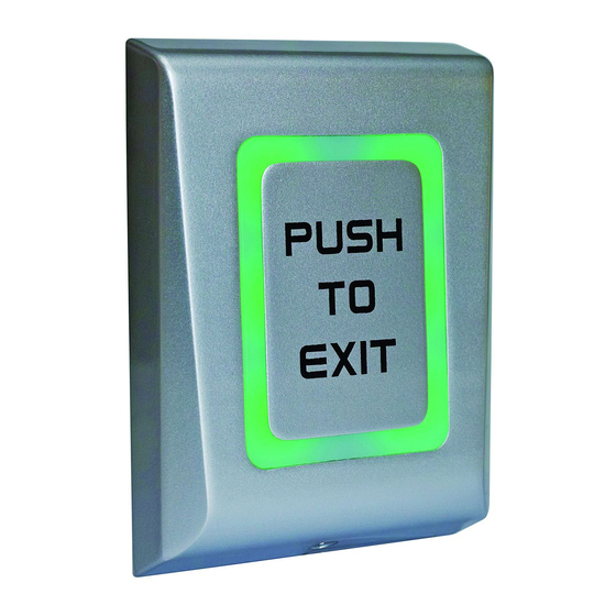
CM-9800
Touch Button Switch
INSTALLATION INSTRUCTIONS
SL NO
Component Name
1
Wall plug 6mm
2
Wall fixing screw 4 x 30mm
3
3 x 6 Security Screw
4
IN4007 diode
5
470nf Capacitor
6
10K Res 1/2w
7
Security screw driver
8
6-32 x 1" Machine screw
9
Mounting Template
1. GENERAL DESCRIPTION
CM-9800 is a request-to-exit switch, It will work independently
(standalone) or can equally be connected via a controller to
provide exit from a secured area (Push Button Input). With its
slim looks and die-cast metal body, the CM-9800 combines
elegance and aesthetics with ruggedness and reliability.
2. SPECIFICATIONS
Input Voltage
12-24V AC/DC
Current
max.65mA
Consumption
Relay Output
2A at 24V DC / 120V AC
Set Relay Time
0.5 to 60 seconds or Toggle (ON/OFF)
Indicators-LED
Orange, red, green
LED Control
Yes, by DIP switch
Tamper
Yes
Backlight ON/OFF
Yes, by DIP switch
Buzzer ON/OFF
Yes, by DIP switch
Operating
-4°F to 122°F (-20°C to 50°C)
Temperature
Operating Humidity
Non-condensing up to 95%
Housing
Die-cast Aluminium alloy
Touch Plate
Mild Steel Painted
Protection
IP66
3.34" W x 4.5" L x 1/32" H
Dimension
(85 mm x 116.6 mm x 22.6 mm)
Quantity
3
3. MOUNTING
3
1
1
1. Identify a suitable location on wall or flat surface.
1
2. Stick the Drilling Template provided on chosen location.
1
Drill 3 holes as indicated in the diagram.
1
3. Insert 3 nos. of 5 mm wall plugs provided into the drilled holes.
2
4. Route the cables through the holes provided in the
1
BackPlate.
5. Fix the Backplate firmly on the wall using 3nos. of 3 x 30mm
CSK screws
6. Connect wires.
7. After wiring, place the Housing over the fixed backplate and
guide the slot into the backplate tab and slide it downwards.
8. Fix the Housing to the Back-Plate with a M3 x 6 mm Security
Screw on the bottom of the Housing using a Security
Screwdriver provided.
Important Note: Several layers of protection are provided
against transient voltages from static discharge, lightning
and power supply spikes. For protection to be fully effective,
earth grounding should be done correctly.
12/24 V
12 to 24VDC
12 to 24VAC
AC/DC
Tamper Switch
Tamp
Tamper Switch
Tamp
Red LED light
LR-
LG-
Green LED light
Normally closed
NC
Common
COM
Normally open
NO
LED com
LED common
(GND)
Red
12/24V
Power Supply
Black
AC/DC
Green
LED com (GND)
Orange
LR -
Yellow
LG -
Pink
NC
White
COM
Relay 2A
Purple
NO
Tamp
Grey
Tamper
Blue
Tamp
Color
Black &
Red
Grey
Blue
Orange
Yellow
Pink
White
Purple
Green
Page 1 of 5