CAMDEN Lazerpoint CM-TXLF Series 설치 지침
{카테고리_이름} CAMDEN Lazerpoint CM-TXLF Series에 대한 설치 지침을 온라인으로 검색하거나 PDF를 다운로드하세요. CAMDEN Lazerpoint CM-TXLF Series 3 페이지. Fob style transmitters
D o o r Ac t iv a ti o n D e v i c e s
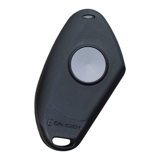
Lazerpoint™ CM-TXLF Series
FOB Style Transmitters
INSTALLATION INSTRUCTIONS
1. GENERAL DESCRIPTION
Camden Lazerpoint™ Radio Controls comprise the following
models:
• CM-TXLF-1, CM-TXLF-2, CM-TXLF-4, CM-TXLF-1LP and
CM-TXLF-2LP Key Fob Transmitters, as well as;
• CM-TX-9 Wall switch ready transmitter
• CM-TX-99 Plug-in 2-Channel Transmitter
• CM-RX-91 Basic Receiver
• CM-RX-92 Full function (dual relay) Receiver.
These instructions cover the TXLF transmitters.
Camden Key Fob transmitters utilize readily available CR-2032
Lithium batteries, and special circuitry to assure long life. A
proprietary bi-colour LED circuit is used to annunciate wireless
activation, low battery, & Battery Gas Gauge™ conditions.
2. SPECIFICATIONS
Models
Buttons / Channels
Frequency
Codes
LED Indicator
Power
Battery Life
Range
Temperature Rating
Dimension
TXLF-1 (FVIN: 3A)
TXLF-2 (FVIN: 3B)
TXLF-4 (FVIN: 3C)
1, 2, & 4 respectively
Operates in the 902 – 928
MHz ISM Band
1 million (20 bit) codes
Used for transmit status (green),
Low Battery, and Battery Gas
Gauge™ indicator (red).
1 x CR-2032 Lithium battery
Minimum 115,000 operations
Over 250 ft (76 m) open area
-40°F to 185°F (-40°C to +85°C)
2 9/16" L x 1 9/16" W x 5/8" D
(102mm x 42mm x 16mm)
2. INSTALLATION
Mounting
Camden TXLF Fobs can be attached to a key chain using the
included ring.
Fobs can also be mounted to a wheelchair by using accessory
number # CM-TXLFB Mounting Base. This unique accessory
converts any of the Mini Fobs to a full size unit which may be
clipped to a belt or sun-visor, or fastened to a desk or counter
for reception use. See our Lazerpoint™ spec sheet or TXLFB
Instruction manual for further details.
The CR-2032 battery is pre-installed in the Fob. Simply press
the button and observe the GREEN LED, which indicates proper
transmission.
Test the battery strength by pressing and holding the button
for approximately 5 seconds. The LED should flash RED 5
times, meaning the battery is at full capacity. This is the Battery
Gas Gauge™ feature. If the LED flashes RED only 1 - 2 times,
you should change the battery for a fresh (new) one. See
instructions at right.
When the battery is low and needs to be changed, the LED will
indicate a slow red flash — 1 flash per second. The unit will still
continue to function (transmit) for a time, but the battery should
be changed as soon as possible.
Learning the Transmitter(s) to the Receiver
To learn the transmitter into an RX-91 or RX-92 receiver, press
the PB1 (or PB2) button on the Receiver using a small blunt
object such as a small blade screwdriver or similar. Within 10
seconds, press the button on the TXLF transmitter. The Green
LED Array will flash once to confirm enrollment. Repeat
withanyadditionaltransmitters. Pressingthe learned transmitter
again will signal the receiver that you are finished programming
and LED's 1 & 2 will flash, in an alternating sequence.
Pressing the transmitter a third time will activate the relay and
corresponding LED, and also the device connected to the relay
contacts.
For multiple button FOBS – TXLF-2 & TXLF-4, learn the desired
button into one receiver, and the other button(s) into additional
receivers. (You could also learn Button 1 into Channel 1 of
the RX-92, and Button 2 into Channel 2 of the same RX-92.)
Refer to the RX-91 or RX-92 receiver for further programming
instructions.
Page 1 of 3