AkitikA STEREO 410 빠른 시작 매뉴얼 - 페이지 8
{카테고리_이름} AkitikA STEREO 410에 대한 빠른 시작 매뉴얼을 온라인으로 검색하거나 PDF를 다운로드하세요. AkitikA STEREO 410 11 페이지. Pc30 replacement

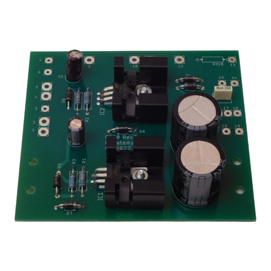
Capacitor Installation
With the exception of C3, all of the capacitors installed here are polarized. Make sure to
align the non-negative side of the capacitor with the plus sign.
Desig Value
C1
2200 uF, 25 Volts
C2
2200 uF, 25 Volts
C3
10 nF, 250V (non-polar)
C4
47 µF, 35 Volts
C5
47 µF, 35 Volts
Removing the Old PC30
Label the following wires prior to removing the old PC30. You may find that
dismounting the old PC30 from its mounting brackets may make this easier. Remove and
reserve the hardware. It will be reused to install the new PC30.
PC30
Description
Eyelet
1
To positive 75V fuse common (fuse block
terminals 3 and 4)
2
To positive diode bridge output, terminal 3
3
+13V output, to PC29 eyelet 18
4
To negative 75V fuse common(fuse block
terminals 7 and 8)
5
To negative diode bridge output, terminal 1
6
Chassis ground lug near C2
7
-13V output, to PC29 eyelet 12
8-13
No connection
14
First blue wire from power transformer
15
No connection
16
Blue/Yellow wire from power transformer
17
Ground connection for PC29 eyelet 15.
18
No connection
19
Second blue wire connection from power
transformer
20
Common Terminal of Dynaguard Lamps DL and
DR
Figure 4-PC-30 connections may be useful to you as you disconnect the wires from the
old PC-30 and reconnect wires to the new PC-30.
Done
Page 8 of 11
Notes about connections on
the PC30
Terminals 1 and 2 are
connected
Terminals 4 and 5 are
connected
Terminals 14 and 15 are
connected
Terminals 16, 17, and 18 are
connected
Terminals 19 and 20 are
connected
