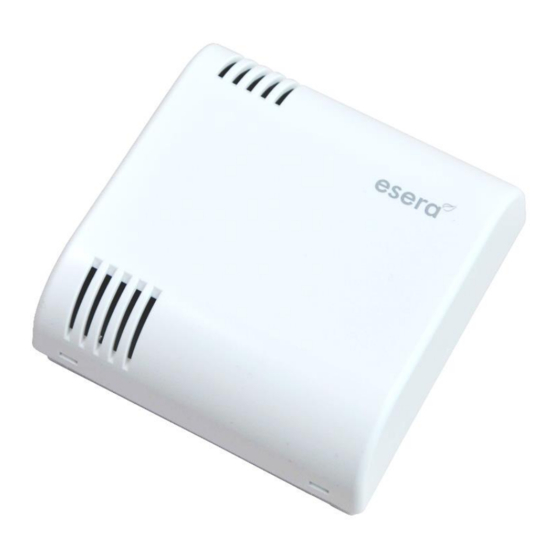
esera 1-Wire Multisensor Pro II 사용자 설명서 - 페이지 6
{카테고리_이름} esera 1-Wire Multisensor Pro II에 대한 사용자 설명서을 온라인으로 검색하거나 PDF를 다운로드하세요. esera 1-Wire Multisensor Pro II 8 페이지. Professional in-wall room sensor for temperature, air humidity and air quality (voc)

15
Terminal assignment
The 1-Wire Multisensor Pro II is connected via Push-In
terminals.
The connection terminal is intended for solid cables
with a cross-section of 0.2 to 2.5qmm or fine-stranded cables
with a cross-section of 0.2 to 1.5qmm. For connection we
recommend slotted screwdriver size of 2,5x75.
The pin assignment is printed on the printed circuit board.
It is necessary to pay attention to the correct polarity when
connecting.
The Multisensor is to be connected with three cables (Ground,
1-Wire Data and 5V). The parasitic mode is not supported.
Note
The module may only be operated at the voltages and under the ambient conditions intended for it. The
operating position of the device is arbitrary.
The modules may only be commissioned by a qualified electrician.
For further information on the operating conditions, see the following instructions under
"Operating conditions".
16
Assembly
The installation location must be protected from direct
moisture (e.g. dripping water) and drafts. The device may
only be used in dry indoor rooms and in protected outdoor
areas.
A location free of drafts must be selected for installation.
The device is intended for installation as a stationary
device. The 1-Wire Multisensor can be ideally mounted on
a flush-mounted box thanks to clever housing cutouts.
Note
The sensor module and the carrier frame are
connected with a narrow ribbon cable. Avoid
mechanically stressing the red connector plugs or
pulling on the ribbon cable.
Overloading may cause irreparable damage.
17
1-Wire Network Cabling
The special feature of the 1-Wire system is the "BUS technology". All devices (sensors and actuators) are
operated in parallel on a three-wire line, which is used for both power supply and data communication. The 1-
Wire bus system joins the list of other successful bus systems such as CAN or Modbus RTU. All of the installation
principles recommended for these are also applicable and appropriate to 1-Wire.
The maximum size of a 1-Wire Network is determined by various factors. These are mainly:
-
Total cable length and cable type
-
Number of 1-Wire devices
-
Type of cable installation (topology)
-
Number and design of cable connectors (unnecessary connection transitions should be avoided)
All factors in total are summarised and referred to as 1-Wire Bus load. Each increase of a factor increases the
total 1-Wire Bus load for the 1-Wire controller and thus reduces the maximum network size.
All rights reserved. Reproduction as well as electronic duplication of this user guide, complete or in part, requires the written consent of
ESERA GmbH. Errors and technical modification subject to change. ESERA GmbH 2021
www.esera.de
11165 V1.0 R1.1 Manual
Page 6 of 8
