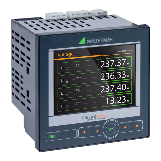
Camille Bauer SINEAX AM1000 안전 지침 - 페이지 4
{카테고리_이름} Camille Bauer SINEAX AM1000에 대한 안전 지침을 온라인으로 검색하거나 PDF를 다운로드하세요. Camille Bauer SINEAX AM1000 16 페이지. Universal heavy current measurement unit

Universal heavy current measurement unit
Safety instructions
Perfect and safe operation requires that these safety inst-
ructions as well as the device handbook have been read and
understood.
www.camillebauer.com/am1000-en
The installation and commissioning should only be carried out by
trained personnel.
Check the following points before commissioning:
– that the connection wires are not damaged, and that they are not live
during wiring,
– that the power flow direction and the phase rotation are correct.
The instrument must be taken out of service if safe operation is no
longer possible (e.g. visible damage). In this case, all the connections
must be switched off. The instrument must be returned to the factory or
to an authorized service dealer.
It is forbidden to open the housing and to make modifications to the
instrument. The instrument is not equipped with an integrated circuit
breaker. During installation check that a labeled switch is installed and
that it can easily be reached by the operators.
The device is maintenance free. Unauthorized repair or alteration of the
unit invalidates the warranty.
Application area
Comprehensive instrument for the universal measurement and monitoring
in power systems. A complete parameterization of all functions is possible
directly at the device or via WEB browser. The universal measurement sys-
tem of the device may be used directly for any power system, from single
phase up to 4-wire unbalanced networks, without hardware modifications.
The nameplate (fig. 1, page 5) on the device gives further details about the
present version.
Mounting
- Devices without top-hat rail adapter are designed for panel mounting.
The necessary panel cutout and the required minimum distances are
shown in figure 2. Slide the device from outside into the cutout and fix it
by means of the two mounting clamps.
- Devices with top-hat rail adapter may be clipped onto a top-hat rail
according EN 60715 (35mm) in a cabinet.
4
www.camillebauer.com/pq1000-en
Electrical connections
A marked and easily accessible current limiting switch has
to be arranged in the vicinity of the device for turning off the
power supply. Fusing should be 10 Amps or less and must be
rated for the available voltage and fault current.
Attention: Danger to life! Ensure that all leads are free of
potential when connecting them!
All voltage measurement inputs must originate at circuit
breakers or fuses rated 5 Amps or less. This does not apply
to the neutral connector. You have to provide a method for
manually removing power from the device, such as a clearly
labelled circuit breaker or a fused disconnect switch.
When using voltage transformers you have to ensure that
their secondary connections never will be short-circuited.
No fuse may be connected upstream of the current measu-
rement inputs!
When using current transformers their secondary connec-
tors must be short-circuited during installation and before
removing the device. Never open the secondary circuit under
load.
The assignment of the connections is as shown on the nameplate. See
example for an unbalanced 4-wire power system (Fig. 3, page 16).
Please observe that the data on the type plate must be
adhered to !
The national provisions (e.g. in Germany VDE 0100 "Condi-
tions concerning the erection of heavy current facilities with
rated voltages below 1000 V") have to be observed in the
installation and material selection of electric lines!
Measurement inputs
U: 600V CAT III, I: 300V CAT III
Nominal current:
adjustable 1...5 A, maximum 7.5 A (sinusoidal)
Nominal voltage:
57.7...400 VLN (UL: 347 VLN),
100...693 VLL (UL: 600 VLL)
maximum 480 V
Nominal frequency:
45 ... 50 / 60 ... 65Hz
Power supply
terminals 13-14
Nominal voltage:
100 ... 230V AC/DC or 24 ... 48V DC
Consumption:
≤ 18 VA, ≤ 8 W, depending on device version
Digital input passive (Fig. 4, page 16)
Tariff switching, status information
Digital inputs passive
Pulse meter, status information
Nominal voltage
12 / 24 V DC (30 V max.)
Digital inputs active (Fig. 5, page 16)
Pulse meter, status information
Digital outputs (Fig. 6, page 16)
Pulse output or alarming
Nominal voltage
12 / 24 V DC (30 V max.)
Relays
optional, see nameplate
Load capacity:
250 V AC, 2 A, 500 VA or 30 V DC, 2 A, 60 W
Safety:
300V CAT III
Analog outputs
optional, see nameplate
Range:
± 20 mA (24 mA max.), bipolar
Burden:
≤ 500 Ω (max. 10 V / 20 mA)
, 832 V
(sinusoidal)
LN
LL
