Camille Bauer SINEAX CAM 사용 설명서 - 페이지 8
{카테고리_이름} Camille Bauer SINEAX CAM에 대한 사용 설명서을 온라인으로 검색하거나 PDF를 다운로드하세요. Camille Bauer SINEAX CAM 12 페이지. Graphic display for sineax cam
Camille Bauer SINEAX CAM에 대해서도 마찬가지입니다: 사용 설명서 (19 페이지)

All measurement values may be read via USB or RS485 in-
terface and displayed using the CB-Manager software. Use
the device menu "visualisation" and the desired measurement
type to go to the appropriate measurement representation and
start the acquisition. The data will be displayed and logged.
The logged data may be stored on disk for future analysis.
6.4 Protecting devices
For each device user rights can be confi gured. The right to
change confi guration data or to set/reset extreme values,
meters or slave pointers may be committed this way se-
lectively for up to 3 different users. To perform appropriate
functions it is then necessary to enter usename and password
in advance.
To be able to defi ne user rights the input of an administrator
login is required. The factory setting is:
User:
admin
Password: admin
ATTENTION: To reset forgotten passwords it's necessary to
send the device back to the factory!
6.5 MODBUS
For customer specifi c MODBUS solutions the protocol and
all necessary information is summarized in the document
"SINEAX CAM Modbus interface". This may be found on
the CD as well.
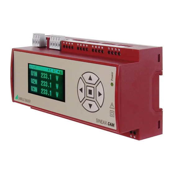
6.6 Graphic display (optional)
The parametrization of the graphic display and the assembling
of user specifi c measurement displays is performed using
the CB-Manager software. Parameters like contrast or the
selection of the display language (English, German, French,
Czech, Spanish, Dutch, Italian) can be set also directly using
the keypad.
The operation of the graphic display is described in a separate
document, which is attached in English and German to all
devices equipped with display. The appropriate manuals for
all languages may be found on the provided software CD.
6.7 Rogowski current inputs (optional)
This version provides instead of current inputs voltage inputs
for connecting the integrator circuit of Rogowski coils. These
can be fi tted quickly and easily without opening the current
circuit and can cover a wide current range. Rogowski coils
can respond to fast-changing currents and transmit harmo-
nics much better than conventional current transformers.
Thus this version is suited for applications where an accurate
analysis of harmonics resp. system feedback is required, as
well as for test facilities, where the device under test must
be replaced often and quickly. The power supply of the
Rogowski coil integrator can be performed via CAM directly.
6.8 Modbus/TCP
The Ethernet communication by means of the Modbus/TCP
protocol is described in the separated document "Modbus/
TCP interface SINEAX CAM" (see documentation CD).
6.9 IEC 61850
The IEC 61850 communication is documented separa-
tely. See documentation on the CD or on our homepage
http://www.camillebauer.com
8
7. Technical data
The complete technical data is given in the data sheet of
the device.
7.1 Measurement input (Terminals 1-12)
Frequency range:
45...50/60...65 Hz or
10...50/60...70 Hz or
10...50/60...140 Hz
Measurement TRMS:
up to the 63
Measurement category: ≤ 300 V CATIII, ≤ 600 V CATII
Current measurement
Rated current:
1 A (+ 20%), 1 A (+ 100%),
5 A (+ 20%), 5 A (+ 100%)
Overriding max.:
10 A (sinusoidal)
Consumption:
≤ I
Thermal ratings:
12 A continuous
100 A, 10 x 1 s, Interval 100 s
Instead of current inputs the version for Rogowski coils
provides voltage inputs of nominal 5 V (max. 10 V).
Voltage measurement
Rated voltage:
57.7 ... 400 V
Overriding max.:
600 V
Consumption:
≤ U
Input impedance:
3 MΩ per phase
Thermal ratings:
480 V
600 V
Interval 10 s
800 V
Interval 10 s
System
Single-phase
Split Phase
3-wire system, balanced load
3-wire system, unbalanced load
3-wire system, unbalanced load (Aron)
4-wire system, balanced load
4-wire system, unbalanced load
4-wire system, unbalanced load (Open-Y)
Basic accuracy under reference conditions
acc. IEC/EN 60 688, sinusoidal 50-60 Hz, 15 to 30 °C
Voltage:
Current:
Power:
Power factor:
Frequency:
Voltage unbalance:
Harmonics:
THD Voltage:
TDD Current:
Energy:
Active energy direct connection:
Active energy transformer connection: Kl. 2 / EN 62 053-21
Reactive energy:
rd
harmonic
2
x 0.01Ω per phase
, 100 ... 693 V
LN
, 1040 V
(sinusoidal)
LN
LL
2
/ 3 MΩ per phase
, 832 V
continuous
LN
LL
, 1040 V
, 10 x 10 s,
LN
LL
, 1386 V
, 10 x 1 s,
LN
LL
1L
2L
3Lb
3Lu
3Lu.A
4Lb
4Lu
4Lu.O
a)
± 0.1% FS
± 0.1% FS
a)
b)
± 0.2% FS
± 0.1°
± 0.01 Hz
± 0.2%
± 0.5%
± 0.5%
± 0.5%
b)
± 0.2% FS
Kl. 1 / EN 62 053-21
Kl. 2 / EN 62 053-23
LL
