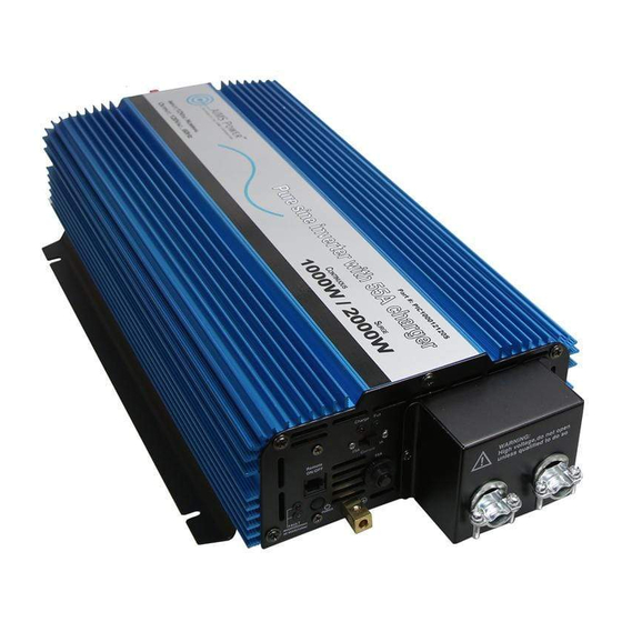
AIMS Power PIC100012120S 사용 설명서 - 페이지 6
{카테고리_이름} AIMS Power PIC100012120S에 대한 사용 설명서을 온라인으로 검색하거나 PDF를 다운로드하세요. AIMS Power PIC100012120S 13 페이지. Pure sine power inverter with charger & transfer switch

2. Battery operating time depends on battery capacity and load. The formula for
operating time is: battery capacity divided by the value of the load divided by
battery voltage times 1.10%. For example, using the numbers from above, the
battery specification is 12V, 200Ah capacity and the load is 1000W. Take battery
capacity 200Ah / 91.6 amps = 2.18 hours of run time if you fully deplete the
battery. This is NOT recommended. Deep cycle batteries last longer when they
are only depleted to 50% of capacity.
F. CONNECTION
1. Grounding
The power inverter has a terminal on the rear panel marked " Grounding "or "≡".
This is used to connect the chassis of the power inverter to ground. The ground
terminal has already been connected to the ground wire of the AC terminal
through the inverter.
The ground terminal must be connected to the ground wire, which will vary
depending on where the power inverter is installed. In a vehicle, connect the
ground terminal to the chassis of the vehicle. In a boat, connect it to the boat's
ground system. In a fixed location, connect the ground terminal to earth.
2. Battery terminals
Before you connect the battery cables, make sure the power switch is in the off
position. Connect Red (+) battery cable to Red (+) inverter terminal. Connect
Black (-) battery cable to Black (-) inverter terminal. Connect Red (+) battery
cable to Red (+) battery terminal. Connect Black (-) battery cable to Black (-)
battery terminal. Alligator clamp cables may be used but only to connect to the
battery. Do not use clamps on inverter terminals. Alligator clamps are not a
permanent solution. You may see a spark during connection. Do not reverse the
polarity. This may damage the inverter and void warranty.
3. Hardwire Connection – AC Wiring. Use 12 AWG wire, fine copper stranded.
Input: Hot line + Neutral + Ground
Output: Hot line + Neutral + Ground
Green – ground
White – neutral
Black - hot
4. If connecting to a breaker panel do NOT neutral ground bond the panel.
