FiTech Go EFI Classic 30020 사용 설명서 - 페이지 5
{카테고리_이름} FiTech Go EFI Classic 30020에 대한 사용 설명서을 온라인으로 검색하거나 PDF를 다운로드하세요. FiTech Go EFI Classic 30020 10 페이지.
Above - The supplied Coolant Temperature Sensor is threaded into
the water port in the intake manifold. Use Teflon tape on threads.
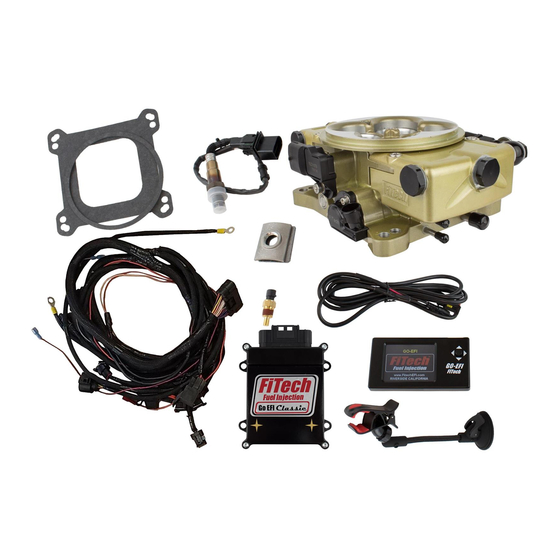
Injectors
Figure 13
Above - The throttle body has four 80-lb injectors already
installed. This arrangement will allow the system to supply enough
fuel flow for up to 650 HP. The throttle body has the injector sub-
harness pre-installed and ready to go.
Wiring the EFI System
See the wire chart (Figure 16 on page 6) which lists each wire
in Harness "A" that is used in the system and what it connects to.
NOTE: Typically some of the wires listed in the chart on the next
page may need to be extended. It is strongly suggested that any
wire ex-tensions are made with the same gauge and color wire as is
used in the supplied harness. Make connections as a soldered
joint rather thanacrimpedconnection.Utilizea shrinkwrapped
sleevecovering all connections.
All
modifications
Figure 15
made to wiring can
only be made on
wires listed in Wire
Chart Figure 16 on
the next page such
as
extensions
or
Ground
cuts.
Any modifica-
tion of the ECU main
Fan 1 - Gray Wire
harness (see Figure
7) other than these
listed wires will result
Fan Circuit
in a VOIDING of the
FiTech EFI warranty.
Figure 11
Injector sub-harness
Fuse
Battery
30
86
85
Relay
87
Ign/Acc
Circuit Fuse
Fan
Figure 12
Above - The CTS connector on the main wiring harness is plugged
into the Coolant Temperature Sensor in the manifold. (1/2" NPT adapter
supplied in kit)
Injector sub harness
connector
See Figure 7. Connect the injector sub-harness onto the main
harness. Make sure the connectors are securely fastened.
On Engine-Adjustments
When you set idle speed, you will notice some new sounds. The first is
ticking from the injectors and it is normal. You may also hear air
whooshing or whistling at idle. Barring a vacuum leak, this is likely the
bypassed air from the Idle Air Control (IAC valve) and this is normal. The
IAC valve maintains idle speed when the AC compressor or electric fans
click on.
IAC Setup
The idle screw on the throttle body needs to be adjusted. This needs to be
set so that the IAC value is nearly closed when fully warmed up and in
idle 3-10 IAC Steps are recommended for a fully warm engine, out of gear,
at idle. When the engine is at idle, the IAC will learn the necessary position
to maintain the RPM at the Target Idle Speed. When loads are placed on
the engine or when the throttle is open, the IAC steps will move around,
this is normal. It's best to adjust this screw from a more open position to
Ground
start with. This will allow the engine to start at a high idle, which will
make adjusting the IAC easier. Follow this procedure:
1. Start the engine and in your Handheld go under "initial set-up."
2. Go to "idle setup" and find "idle set mode" and switch to "Adjust"
3. Start the vehicle and find IAC Steps on the dashboard. This number
needs to be within 3-10 at operating temperature. If the number reads
Ground
zero then slowly turn the screw OUT (counterclock-wise) until the IAC
Steps reads between 3-10.
5
Figure 14