Altronix TMV2 설치 매뉴얼 - 페이지 2
{카테고리_이름} Altronix TMV2에 대한 설치 매뉴얼을 온라인으로 검색하거나 PDF를 다운로드하세요. Altronix TMV2 16 페이지. Access & power integration
Altronix TMV2에 대해서도 마찬가지입니다: 설치 매뉴얼 (16 페이지), 설치 매뉴얼 (4 페이지), 설치 매뉴얼 (20 페이지)
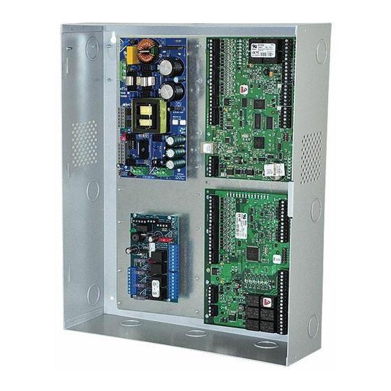
Trove2M2 or Trove2V2 accommodates various combinations of Mercury or HID VertX boards with or without Altronix
power supplies and accessories for access systems.
• 19 Gauge grey enclosure with ample knockouts for convenient access.
Enclosure Dimensions (H x W x D): 27.25" x 21.75" x 6.5" (692.15mm x 552.45mm x 165.1mm)
Trove2M2
- Trove2 enclosure with TM2
Altronix/Mercury backplane.
• Includes: tamper switch, cam lock,
lock nuts and mounting hardware.
Trove2M2 accommodates a
combination of the following:
• Two (2) eFlow3NB, eFlow4NB,
eFlow6NB, eFlow102NB or
eFlow104NB.
• Four (4) ACM4(CB), ACM8(CB),
MOM5, PD4UL(CB), PD8UL(CB).
• Six (6) EP1502, MR52, MR16IN,
MR16OUT.
• Six (6) EP2500 or MUX8.
• Five (5) MR51e.
• Two (2) MR50.
Wiring methods shall be in accordance with the National Electrical Code/NFPA 70/ANSI, and with all local codes and
authorities having jurisdiction. Product is intended for indoor use only.
1. Remove backplane from enclosure. Do not discard hardware.
2. Mount unit in the desired location. Mark and predrill holes in the wall to line up with the top three keyholes in the
enclosure. Install three upper fasteners and screws in the wall with the screw heads protruding. Place the enclosure's
upper keyholes over the three upper screws, level and secure. Mark the position of the lower three holes. Remove the
enclosure. Drill the lower holes and install the three fasteners. Place the enclosure's upper keyholes over the three
upper screws. Install the three lower screws and make sure to tighten all screws (Enclosure Dimensions, pg. 10).
3. Mount included UL Listed tamper switch (Ademco model 112 or equivalent) at the top of the enclosure.
Slide the tamper switch bracket onto the edge of the enclosure approximately 2" from the right side (Fig. 1, pg. 2).
Connect tamper switch wiring to the Access Control Panel input or the
appropriate UL Listed reporting device.
To activate alarm signal open the door of the enclosure.
4. Mount Altronix/Mercury/HID VertX boards to backplane, refer to pages 3-12.
Hardware:
Male/Female Standoff
Standoff (Metal or Nylon)
5/16" Pan Head Screw
7/8" Pan Head Screw
Lock Nut
- 2 -
Specifications:
Trove2V2
- Trove2 enclosure with TV2
Altronix/HID VertX
• Includes: tamper switch, cam lock,
lock nuts and mounting hardware.
Trove2V2 accommodates a
combination of the following:
• Two (2) eFlow3NB, eFlow4NB,
eFlow6NB, eFlow102NB or
eFlow104NB.
• Four (4) ACM4(CB), ACM8(CB),
MOM5, PD4UL(CB), PD8UL(CB).
• Six (6) V100, V200, V300,
V1000 or V2000.
Trove2M2, Trove2V2 Installation Instructions:
Overview:
®
backplane.
Backplanes Only:
TM2
- Altronix/Mercury backplane only.
• Includes: lock nuts and
mounting hardware.
TV2
- Altronix/HID VertX
backplane only.
• Includes: lock nuts and
mounting hardware.
Optional Door Backplane:
TMV2
- Mercury or HID VertX
door backplane only.
• Includes: lock nuts and
mounting hardware.
Fig. 1
Honeywell
model # 112
Tamper Switch
or equivalent
(provided)
to Access Control Panel
or U.L. Listed
Reporting Device
Altronix/Mercury/HID VertX Enclosure
®
®
Enclosure
Edge of
Enclosure