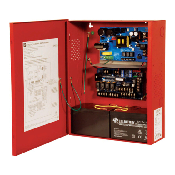
Altronix AL1002ADA220 설치 매뉴얼 - 페이지 6
{카테고리_이름} Altronix AL1002ADA220에 대한 설치 매뉴얼을 온라인으로 검색하거나 PDF를 다운로드하세요. Altronix AL1002ADA220 17 페이지. Nac power extender
Altronix AL1002ADA220에 대해서도 마찬가지입니다: 애플리케이션 매뉴얼 (8 페이지)

AL800LGK9E Logic Board
Terminal Legend
IN1 +, IN1 –
IN2 +, IN2 –
(Supervised)
RET1 +, RET1 –
RET2 +, RET2 –
(Supervised)
C "DRY1" NC
C "DRY2" NC
(Dry input trigger)
+ OUT1 –
+ OUT2 –
+ OUT3 –
+ OUT4 –
(Supervised)
C "FAULT" NC
(Common
trouble input)
NC, C, NO
(Common
trouble output)
– AUX +
– DC +
Note: Unit is equipped with 1A max. auxiliary output: "AUX" will remain battery backed up during
power outage. For loads connected to "AUX" please refer to battery "Stand-by Specifications", pg. 3
for ratings. When loads are connected to "AUX" output during alarm condition, the remaining outputs
may not exceed 10A total alarm current (example: AUX = 1A, outputs up to 10A).
- 6 -
Terminal Identification Table:
Function/Description
These terminals connect to the 24VDC FACP notification appliance circuit outputs. (Class
A or Class B) Input trigger voltage is 8-33VDC @ 6.5mA min. Terminal polarity is shown
in alarm condition. During an alarm condition these inputs will cause the selected outputs
chosen to drive notification appliances. The designated outputs are set by output switches
[OUT1 through OUT4] (Output Programming Selection Table, pg. 5). A trouble condition on
an output loop will cause the corresponding input to trip the FACP by opening the FACP
loop. An alarm condition will always override trouble to drive notification appliances. Rated
12V 6.5mA, 24V 6.5mA.
For Class A hookups these terminal pairs return to FACP NAC1 and/or NAC2.
For Class B hookups the FACP EOL resistor from the NAC1 and/or NAC2 outputs are
terminated at these terminals.
An open across these inputs, will cause the selected outputs chosen to drive notification
appliances. The designated outputs are set by output switches [OUT1 through OUT4]
(Output Programming Selection Table, pg. 5). Note these inputs are unidirectional and
will not report a trouble condition to the FACP.
Notification appliances are connected to these regulated outputs (see 02 Application
Guide pg. 2-4). Each power-limited output will supply 2.5A. Total supply current is 10A
(see note below). Outputs are controlled by designated Input 1 [IN1] or Input 2 [IN2]
(Output Programming Selection, pg. 5)
An open circuit across this pair of terminals will cause [IN1 and IN2] to simultaneously
signal a trouble condition back to the FACP (Typically used to report AC or BAT Fail).
Form "C" contact 1A / 28VDC (Fig. 8, pg. 11).
These are dry contact trouble outputs that follow any general loop/system trouble
conditions. (Typically used to trigger a digital communicator or other reporting device).
Form "C" contact 1A / 28VDC, 0.35 Power Factor (Fig. 8, pg. 11).
This separate 1A max auxiliary Special Application Power output circuit is Non-
Supervised, Class E. See attached list of devices (Appendix A, pgs. 14-17).
24VDC from power supply.
AL1002ADA220 Installation Guide
