Altronix AL1012X220 Series 설치 매뉴얼
{카테고리_이름} Altronix AL1012X220 Series에 대한 설치 매뉴얼을 온라인으로 검색하거나 PDF를 다운로드하세요. Altronix AL1012X220 Series 4 페이지.
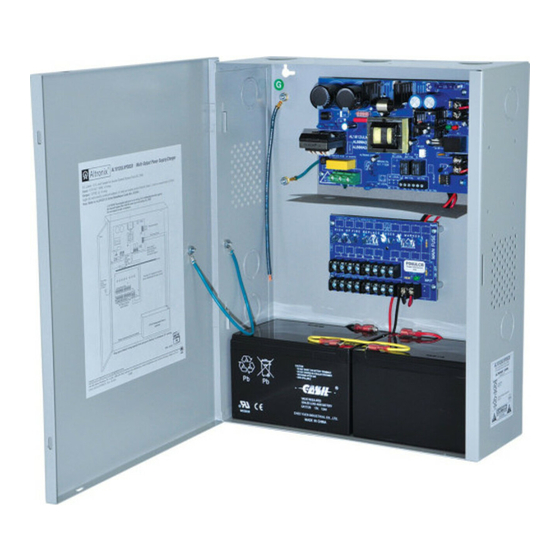
AL1012X220 is a power supply that converts a nominal 220VAC (working range 198VAC-256VAC) 50/60Hz input to a
12VDC output (see specifications).
AL1012X220 is a base unit for a series of multi-output power supply/chargers including: AL1012XPD4220,
AL1012XPD4CB220, AL1012XPD8220, AL1012XPD8CB220, AL1012XPD16220, AL1012XPD16CB220
(Refer to AL1012X220 Series Power Supply Configuration Reference Chart).
AL1012X220 Series Power Supply Configuration Reference Chart:
Altronix
Model Number
AL1012X220
AL1012XPD4220
AL1012XPD4CB220
AL1012XPD8220
AL1012XPD8CB220
AL1012XPD16220
AL1012XPD16CB220
Input:
• Input 220VAC (working range 198VAC - 256VAC),
50/60Hz, 1.3A.
• AC input and DC output LED indicators.
Output:
• 12VDC output.
• 10A total supply current at 12VDC.
• Filtered and electronically regulated outputs.
• Short circuit and thermal overload protection.
Battery Backup:
• Maximum charge current 0.7A.
• Built-in charger for sealed lead acid or gel type batteries.
Wiring methods should be in accordance with the National Electrical Code/NFPA 70/NFPA 72/ANSI and with all local
codes and authorities having jurisdiction. Product is intended for indoor use only.
1. Mount unit in the desired location. Mark and predrill holes in the wall to line up with the top two keyholes in the
enclosure. Install two upper fasteners and screws in the wall with the screw heads protruding. Place the enclosure's
upper keyholes over the two upper screws; level and secure. Mark the position of the lower two holes. Remove the
enclosure. Drill the lower holes and install the fasteners. Place the enclosure's upper keyholes over the two
upper screws. Install the two lower screws and make sure to tighten all screws (Enclosure Dimensions, pg. 4).
Secure enclosure to earth ground.
2. Connect AC circuit (220VAC, 50/60Hz) as follows: Green branch wire connects to earth (safety) ground lug
Line and Neutral to the connector on power supply board marked [L, N] respectively (Fig. 1, pg. 3).
Use 14 AWG or larger for all power connections (Battery, DC output, AC input).
Use 22 AWG to 18 AWG for power-limited circuits (AC Fail/Low Battery reporting).
3. Mea sure output voltage before connecting devices. This helps avoiding potential damage.
Keep power-limited wiring separate from non power-limited wiring (220VAC 50/60Hz Input, Battery Wires).
Minimum 0.25" spacing must be provided.
CAUTION: Do not touch exposed metal parts. Shut branch circuit power before installing or servicing equipment.
There are no user serviceable parts inside. Refer installation and servicing to qualified service personnel.
4. Connect devices to be powered:
a. For Power Supply Board: connect to the terminals marked [– DC +] (Fig. 1, pg. 5).
b. For Power Distribution Module(s): connect devices to be powered to the terminal pairs 1 to 4 marked
[1P & 1N] through [4P & 4N] (Fig. 2, pg. 6) or 1 to 8 marked [1P & 1N] through [8P & 8N] (Fig. 3, pg. 6),
carefully observing correct polarity.
AL1012X220 Series
Installation Guide
Accessory Power
Distribution
Number of
Module(s)
Outputs
-
PD4
PD4CB
PD8
PD8CB
Two (2) PD8
Two (2) PD8CB
Specifications:
Installation Instructions:
Overview:
Fused
Outputs
1
-
P
4
-
P
8
-
P
16
-
Battery Backup (cont'd):
• Automatic switch over to stand-by battery when AC fails.
• Zero voltage drop when switched over to battery backup.
Supervision:
• AC fail supervision (form "C" contacts).
• Low battery supervision (form "C" contacts).
Added Features:
• Power supply, enclosure, cam lock, and battery leads.
Enclosure Dimensions (H x W x D):
15.5" x 12" x 4.5" (393.7mm x 304.8mm x 114.3mm)
PTC Outputs
Individual Output
(auto-resettable)
-
-
P
-
P
-
P
CAUTION: De-e
against risk of ele
and rating 15A, 3
Door
Wire Strap
Rating (A)
10A
3.5A
2.5A
3.5A
2.5A
3.5A
2.5A
.
5A 250V
220 pow