Altronix NetWaySP1BT Series 설치 매뉴얼 - 페이지 4
{카테고리_이름} Altronix NetWaySP1BT Series에 대한 설치 매뉴얼을 온라인으로 검색하거나 PDF를 다운로드하세요. Altronix NetWaySP1BT Series 12 페이지. 802.3bt media converter/injectors
Altronix NetWaySP1BT Series에 대해서도 마찬가지입니다: 설치 매뉴얼 (8 페이지)
Wiring methods shall be in accordance with the National Electrical Code/NFPA 70/ANSI, and with all local
codes and authorities having jurisdiction . All units should be installed by a trained service personnel .
Installation:
NetWaySP1BT:
1 . Mount NetWaySP1BT in desired location utilizing the mounting hole (Fig. 1a, pg. 4) . Use a proper fastener
and/or wall anchor when securing NetWaySP1BT with screw through its mounting hole to the wall .
NetWaySP1BTWPN, NetWaySP1BTWP, NetWaySP1BTWPX:
2 . Remove backplane from enclosure prior to drilling . Do not discard hardware .
Note: Make sure that hardware will not interfere with components of the circuit board .
3 . Mark and drill desired inlets on the enclosure to facilitate wiring. Maximum NEMA type 4X rated fittings
to be used are 0 .5" . Follow manufacturer's specifications for the appropriate size opening .
Note: Inlets for conduit fittings should only be made on the bottom of the enclosure .
To facilitate wire entry utilize weather-tight NEMA rated connectors (supplied), bushings, and cable .
4 . Clean out the inside of enclosure before remounting circuit boards/backplane .
5 . Mounting NEMA4/4X rated enclosure (Enclosure Dimensions, pg. 10, 11, 12):
Wall mount:
Pole Mount:
6 . Mount backplane in enclosure with hardware .
Power Connection:
NetWaySP1BT, NetWaySP1BTWPN:
1 . Use external 48-55V UL Listed ITE power supply, carefully observing correct polarity (Fig. 1, 2, pg. 4) .
NetWaySP1BTWP, NetWaySP1BTWPX:
Before powering unit, set input voltage selection switch to proper Input Voltage position (Fig. 3a, pg. 4).
Units are factory set for 115VAC.
2 . Connect AC power from overcurrent protective device circuit breaker
(20A @ 115VAC, 60Hz or 16A @ 230VAC, 50/60Hz) to the terminals marked [L, N] on power supply
board (Fig. 3, pg. 5) . Connect ground lug to earth or green branch wire on backplane (12AWG min .) .
Use 14AWG or larger for all power connections (Battery, DC output, AC input) .
Keep power-limited wiring separate from non power-limited wiring by utilizing separate knockouts/
inlets. Minimum 0.25" spacing must be provided.
CAUTION: Do not touch exposed metal parts. Shut branch circuit power before installing or servicing
equipment. There are no user serviceable parts inside. Refer installation and servicing to qualified
service personnel.
3 . Battery Backup (if desired): Connect four (4) 12VDC batteries wired in series to terminals marked
[– BAT +] (Fig. 3, pg. 5), carefully observing polarity .
When use of stand-by batteries is desired, they must be lead acid or gel type .
Note: When batteries are not used, a loss of AC will result in the loss of output voltage .
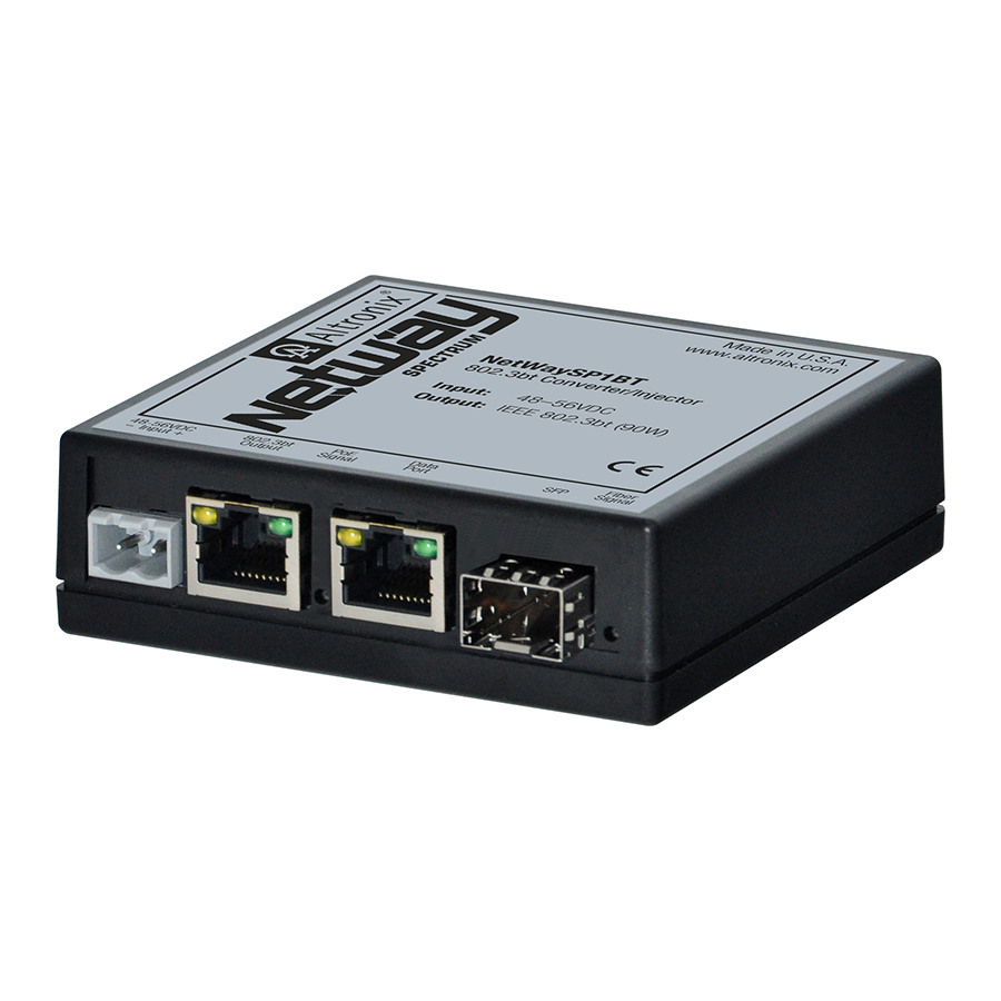
Fig. 1
NetWaySP1BT
802.3bt Converter/Injector
Input:
Output: IEEE 802.3bt (90W)
48-56VDC
802.3bt
PoE
-- Input +
Output
Signal
48-56VDC
-- Input +
- 4 -
Installation Instructions:
Mount unit in desired location . Mark and drill holes to line up with the top and bottom
hole of the enclosure flange . Secure enclosure with appropriate fasteners (e . g . screws
and anchors; bolts and locking nuts, etc .) that are compatible with mounting surface and
are of sufficient length/construction to ensure a secure mount (Fig. 6, pg. 8) .
Refer to Fig. 7 - 11, pg. 8 .
Fig. 1a
48–56VDC
Fiber
Data
SFP
Signal
Port
NetWaySP1BT
802.3bt Converter/Injector
Input:
48–56VDC
Output: IEEE 802.3bt (90W)
48-56VDC
802.3bt
PoE
Fiber
Data
-- Input +
Output
Signal
SFP
Signal
Port
48-56VDC
-- Input +
Fig. 2
NetWaySP1BT Series