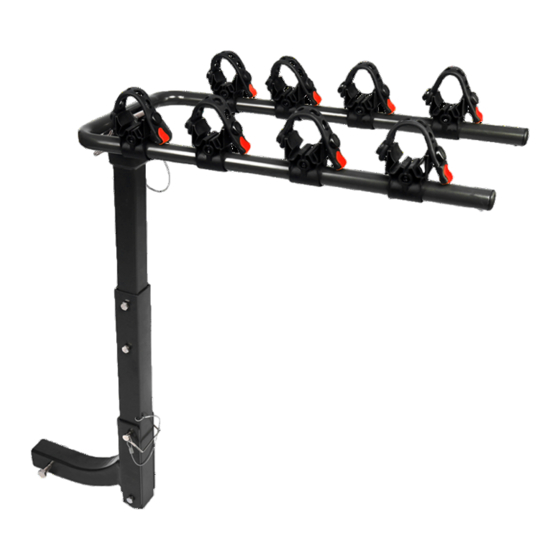
DK2 BCR290 설치 매뉴얼 - 페이지 9
{카테고리_이름} DK2 BCR290에 대한 설치 매뉴얼을 온라인으로 검색하거나 PDF를 다운로드하세요. DK2 BCR290 12 페이지. Hitch mounted bike carrier

ENGLISH
USE
1. Check that all the bicycles are fastened securely and
that they are stable.
2. Check the clearance. It is the responsibility of the driver
to ensure there is sufficient clearance. This is dependent
on the vehicle, the load, and the road. Clearance should
allow for the distance away from the rear wheels and
the movements imposed by driveway ramps and speed
bumps. It should be between 30 and 38 cm (12 and
15 in.).
NOT IN USE
The typically horizontal
"U" tube arms can be
folded down so they
are out of the way
when not carrying
a
bicycles (fig.8, right).
This may in fact be a
legal requirement in
some jurisdictions.
Check your local
laws. Remove the P2
clevis pin from the hole
(at b, fig.8, left), fold
the U-arms down and
re-insert the clevis pin
into the other hole (as
in fig.8 right, a).
ACCESS
To access the rear of
the vehicle, for loading
the trunk or such, the
whole carrier assembly
can be swung out
of the way. Remove
the P1 clevis pin and
support the bike rack
while lowering it out of
the way.
WARNING! This
should not be
attempted with the
weight of a full load of
bicycles.
fig.9
fig.8
FRANÇAIS
UTILISATION
1. Vérifiez que tous les vélos sont suspendus en toute
sécurité et qu'ils soient stables.
2. Contrôlez le dégagement. Il est de la responsabilité
du conducteur de s'assurer qu'il y a un dégagement
suffisant. Cela dépend du véhicule, de la charge et de
la route. Le dégagement devrait permettre une bonne
distance des roues arrière et aussi les mouvements
créés par les rampes d'allée et les bosses de
décélération. Le dégagement devrait être entre 30 et 38
cm (12 à 15 po).
b
b
HORS SERVICE
Le bras tubulaire
en «U» placé a
l'horizontale quand
utilisé peut être repliés
quand non utiliser
pour le transport de
vélos (fig.8, droite).
Cela peut en fait
être une obligation
légale dans certaines
juridictions.
Vérifiez vos lois
locales. Retirez la
goupille P2 du trou
(en b, fig.8, gauche),
rabattez les bras en U
et réinsérez la goupille
dans l'autre trou
(comme sur la figure 8
à droite en A).
ACCÈS
Pour accéder à
l'arrière du véhicule,
pour charger le
coffre l'ensemble
du transporteur
l'assemblage peut
être pivoté. Retirer
la goupille P1 qui
soutient le porte-vélos
et abaisser le support à
vélos.
ATTENTION! Cette
manœuvre ne devrait
pas être tentée avec
les vélos montés sur
le support.
v.200401
9
