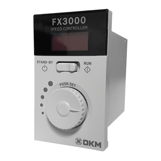
DKM Motor Co., Ltd. FX3000 매뉴얼 - 페이지 2
{카테고리_이름} DKM Motor Co., Ltd. FX3000에 대한 매뉴얼을 온라인으로 검색하거나 PDF를 다운로드하세요. DKM Motor Co., Ltd. FX3000 2 페이지. Digital speed torque controller

How to mount controller
BOLT(M4)
FRONT COVER
■ How to install
→ Process the hole on the mounting panel to attach the controller.
→ Fix the mounting panel and controller body with M4 bolt and nut.
→ Cover the front cover after controller installation, operation and parameter setting.
■ Caution
→ Install without gap between the controller and the mounting panel.
→ The screw head fixed with controller should be below 3mm. If over 3mm,
front cover can't be amounted.
Each part name and Dimension
\
2-Ø4.5
Display
STAND-BY/RUN switch
Mode button
CW/CCW switch
Speed control and
set button(dial)
(7.5)
11
Image without Front cover
Connection
1. Controller Power Connection
AC POWER
INPUT
SW1
CN1
F.G
→AC power: Connect #1 and #2 on terminal CN1.
→ Earth: Connect #3 on terminal CN1.
SW1
Over AC 125V or 250V 5A
<Back side of FX3000>
Mounting Panel Dimension
2-Ø4.5
Mounting
Panel
NUT
52
+1.0
+0.5
Below 3mm
M4 button-head cap screw
CN3
CN1: Power Terminal &
CN1
CW/CCW signal
CN2: Motor Terminal
CN3: Motor Connector
CN2
※Caution: Connect only
CN2 or CN3 when
95
(20)
connecting motor and
controller.
(133.5)
■ Lead wire connection
Orange Color
→ Input the lead wire while pressing the
Button
orange color button with screw driver.
※ Lead wire
- AWG18~14(0.75~2.0 ㎟)
2. CW/CCW Signal connection
SW2
FWD(CW)
CN1
COM
REV(CCW)
SW3
(External Control)
3. Connection of motor and controller
1) Wiring Diagram of Speed Control Motor or Torque Motor
Motor Connector Connection
Connection
CN3
→ Connect motor
connector to
CN1
MOTOR
controller terminal CN3
Motor
Connector
CN2
T.G
FAN
※ Regarding terminal CN1 wiring, please refer to the 'controller power connection' or 'CW/CCW signal connection' in the manual.
※ According to the motor type, TG wire(grey*2) and powerful fan wire(black*2) may not be in.
2) SPEED CONTROL BRAKE MOTOR Connection Diagram
Below diagram is the Brake wiring. Regarding other motors, please refer to the speed control motor or torque motor connection.
Motor Connector or Lead Wire Connection
Ro Co
CN3
CN1
SW1
CN2
3) SPEED CONTROL CLUTCH &
BRAKE MOTOR Connection Diagram
4) Connection Diagram for other brand motor
Motor Connector or Lead Wire Connection
BRAKE
Red
CLUTCH
Red
CN3
&
Blue
BRAKE
DC24V
CLUTCH
Blue
CN1
MOTOR
CN2
※ CLUTCH & BRAKE Power
must be DC24V Separately
T.G
from FX3000.
FAN
-This diagram is the Clutch&Brake Connection.
※ Depending on the motor type and specifications, T.G and powerful fan could not be in.
Regarding other type motors, please refer to the
※ Do not connect to CN3 when connecting other brand motor.
speed control motor or torque motor wiring.
* In case of RUN/ STOP operation externally, please make sure that
switch position should be on STAND-BY and connect to
terminal CN1 #4, #5, #6.
SW2
SW3
Motor shaft
ON
OFF
Rotate to FWD
OFF
ON
Rotate to REV
OFF
OFF
Stop
※ When using the front panel 'STAND-BY/RUN switch' or
'forward/reverse switch', Do not connect terminal 'CN1' #4,#5,#6
in the real panel. (terminal 'CN1' #4, #5, #6: Connect only for
external operation/stop.)
Motor Lead Wire Terminal Block Connection
CN3
CN1
CN1
White
Blue
MOTOR
Red
CN2
CN2
T.G
Gray x 2
FAN
AC POWER
INPUT
SW1
Over AC 125V or 250V 5A
MOTOR
Ro = 5~200Ω(Over 1/4W)
Ro
Co = 0.1 ~ 0.2uF
Co
BRAKE
(AC 200 or 400WV)
T.G
Co, Ro : CR Circuit for surge suppression
FAN
Motor Lead Wire Connection
회사
'O'사
L/W
A(M)
Black
Black
B(M)
Red
White
C(M)
White
Gray
D(T.G)
Blue
E(FAN) Orange Yellow Yellow
* Other brand motor can be
connected to the controller.
Please contact us before use.
Black x 2
'S'사
'G'사
Black
Red
White
Red
Blue
