DLS CC-500 설치 및 운영 방법 - 페이지 2
{카테고리_이름} DLS CC-500에 대한 설치 및 운영 방법을 온라인으로 검색하거나 PDF를 다운로드하세요. DLS CC-500 12 페이지. Dls amplifier
DLS CC-500에 대해서도 마찬가지입니다: 사용자 설명서 (12 페이지)
The models include the following
features:
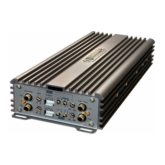
- Analogue class AB or D technique
- High efficiency
- Low profile design
- RCA line inputs
- High level input with auto start
- Powerful DC cable terminals
- Built-in active crossovers
- Remote sub level control on CC-500 /
CC-1000
Installation
Before you begin installation
Before you begin you need to read the manual, to
have some tools, cables and other material available.
There is one such list of material on the following page.
Amplifier location
Important
Allow air circulation around the amplifier.
The DLS series of amplifiers have a compact
design that allows great flexibility in mounting. You
can mount it under a seat or in the trunk.
When you select a location, do remember that the
amplifier generates a lot of heat.
Choose a location where air can circulate freely
around the amplifier. Do not cover the amplifier
with carpets or hide behind trim panels.
Do not mount the amplifier in an inverted or upside
down position.
Check all locations and placements carefully be-
fore making any cuts, drilling any holes or making
any connections.
IMPORTANT!
Use the metal screws coming with the amplifier
when you do the install. Do not use oversized
screws.
Disconnect Battery
Before starting the instal-
lation, always disconnect
the negative terminal of
the battery.
2
Routing wires
Stereo
head unit
Professional Tip:
If amplifier installation kits are available with dif-
ferent size of power cable, chose the most heavy
power cable to improve sound quality and to allow
more amplifiers to be installed now or later.
The amplifier power terminals on CC-2, CC-4 &
CC-44 accept AWG 5 cables, so If possible buy
AWG 5 = 16 mm
cable for best performance.
2
CC-500 & CC-1000 accepts AWG 2 = 33 mm
wer cable. Both the positive wire and the ground
wire must have the same size.
NOTE!
To avoid cable fire, be sure not to oversize the
main fuse value for the power wires.
THE DC-FEED
Maximum main fuse values for different cable
sizes.
6 mm
(9 AWG) :25 A
2
16 mm
(5AWG)
:60 A
2
33 mm
(2AWG) :150 A
2
po-
2
10 mm
(7AWG)
: 40 A
2
21 mm
(4AWG)
: 100 A
2
42 mm
(1AWG)
: 200 A
2