Fleck 5600 Econominder 설치 지침 매뉴얼 - 페이지 9
{카테고리_이름} Fleck 5600 Econominder에 대한 설치 지침 매뉴얼을 온라인으로 검색하거나 PDF를 다운로드하세요. Fleck 5600 Econominder 19 페이지.
Fleck 5600 Econominder에 대해서도 마찬가지입니다: 소유자 매뉴얼 (8 페이지), 설치 매뉴얼 (11 페이지)
between the float and the brine well to secure the overflow nut you can remove the float by removing
the nut that holds the float in place. Make sure to put it back when you are finished.
4 4 . . 2 2 — — U U s s e e 3 3 / / 8 8 i i n n c c h h l l i i n n e e t t o o c c o o n n n n e e c c t t b b r r i i n n e e t t a a n n k k t t o o c c o o n n t t r r o o l l h h e e a a d d
IIm mg g 9 9 -- B Br riin ne e F Fiit tt tiin ng g
pulling the tubing out. The other end of the tubing will connect to the control head. Place the fittings on
the tubing as shown—I I m m g g 1 1 0 0 —and connect it to the control head.
4 4 . . 3 3 — — C C o o n n n n e e c c t t o o v v e e r r fl flo o w w t t o o fl flo o o o r r d d r r a a i i n n
If you have a floor drain available you can connect the overflow fitting to it using a flexible line.
n n o o t t c c o o n n n n e e c c t t t t h h e e o o v v e e r r fl flo o w w t t o o t t h h e e d d r r a a i i n n l l i i n n e e f f r r o o m m t t h h e e c c o o n n t t r r o o l l h h e e a a d d o o r r r r u u n n t t h h e e l l i i n n e e a a b b o o v v e e t t h h e e l l e e v v e e l l o o f f
t t h h e e o o v v e e r r fl flo o w w o o u u t t l l e e t t . . * * ! ! * *
4 4 . . 4 4 — — A A d d d d s s a a l l t t t t o o t t h h e e b b r r i i n n e e t t a a n n k k , ,
Add salt to the brine tank. We recommend high quality pelleted softener salt for the best results. You
will need to add at least one bag of salt and can fill it up to the top of the brine well. Ensure there is salt
in the brine tank at all times.
precharged and able to treat the water out of the box and the initial regeneration ran after installing
the system will place the initial volume of water in the brine tank.
5 5 — — S S
C C
E E T T U U P P
O O N N T T R R O O L L
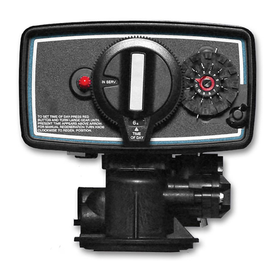
5 5 . . 1 1 — — P P l l u u g g c c o o n n t t r r o o l l h h e e a a d d i i n n
Plug the control head into a qualifing outlet as stated in the requirements section.
The contol head can be plugged in and operated without water, this will not damage the control head.
Once plugged in, verify the system is receiving power and ensure the outlet is not on a switch that
might get turned off. On digital valves the display should light up and start flashing a time, on
The brine line will connect from
the brine fitting on the control
head—I I m m g g 9 9 —to the fitting on
the float inside the brine tank.
To attach it to the float put the
tubing through the hole in the
brine tank and push the tubing
into the fitting until in stops,
then push a little harder to get it
to lock in place. To remove the
tubing, hold the collet ring that
sits around the tubing while
* * * * O O p p t t i i o o n n a a l l * * * *
* * * * w w a a t t e e r r i i s s n n o o t t n n e e c c e e s s s s a a r r y y * * * *
* * * * Y Y o o u u d d o o N N O O T T n n e e e e d d t t o o a a d d d d w w a a t t e e r r t t o o t t h h e e b b r r i i n n e e t t a a n n k k . . * * * *
H H
E E A A D D
9 of 19
IIm mg g 1 10 0 -- B Br riin ne e L Liin ne e F Fiit tt tiin ng gs s
* * ! ! * * D D o o
The resin is
* * * * P P l l e e a a s s e e N N o o t t e e : : * * * *