Fleet Management MLT-400i 설치 매뉴얼 - 페이지 4
{카테고리_이름} Fleet Management MLT-400i에 대한 설치 매뉴얼을 온라인으로 검색하거나 PDF를 다운로드하세요. Fleet Management MLT-400i 14 페이지.
MLT-400i Installation Guide
1
Introduction
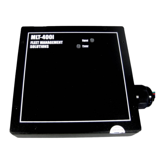
This installation manual covers the installation of the MLT-400i and MLT-400iO.
The MLT-400i/O includes a GPS receiver and a two-way satellite communications modem.
Options include a built-in, on-board diagnostic interface (OBDII), an in cab Message Display
Terminal (MDT) and ignition disable relay.
Recommended Equipment
• Digital Volt/Ohm Meter (DVOM)
• Soldering iron/solder
• Wire strippers/cutters
• Cordless Drill
• Drill bits (step bit or Unibit, #36,
19/32", etc.)
• Flash light
• Standard and Metric socket set
• Screwdrivers (standard, Phillips,
Hex, Torx)
Installation Documentation
Appendix B includes an
v
alidation information.
• The checklist is designed to be com-
pleted in two phases. Phase 1 is instal-
lation inform
ation. Phase 2 is system
validation.
• You will need to locate the Electronic
Serial Number on the label located on
the back of the unit. This identifies
Vehicle Name(Asset Name) to the
modem IMEI Serial Number(ESN):
11/18/2009
Installation Checklist to capture required installation and system
the
FMS MLT-400i Installation Guide 4.3
Recommended Supplies
• Electrical tape
• Velcro
• Silicon
sealant
• Tie-Wraps
• Sheet metal
screws
• 18 gauge wire
• 2 amp ATC fus
• Torque Seal (blue
deterrent
Introduction
e
) for tamper
4