FLENDER ZAPEX 사용 설명서 - 페이지 8
{카테고리_이름} FLENDER ZAPEX에 대한 사용 설명서을 온라인으로 검색하거나 PDF를 다운로드하세요. FLENDER ZAPEX 16 페이지. Couplings
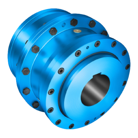
3.
Fitting
The clutch parts are supplied in finished condition in accordance with the order.
3.1
Placing the coupling parts (1; 3) in the case of shafthub connection with parallel key
Clean holes and shaft ends.
Coupling parts (1; 3) with tapered bore and parallelkey connection must be mounted
in cold condition and secured with suitable end plates.
In the case of coupling parts (1; 3) with cylindrical bores the set screws must be unscrewed from the
coupling parts (1; 3).
Fit coupling parts, heating them to max. 80 °C, if necessary.
Shafts must not project from the inner sides of the hub.
When the parts have cooled to room temperature, insert the set screws (for tightening torques, see table 3)
or axially secure the coupling part with the end plate.
3.2
Mounting of coupling parts (1; 3) in the case of a cylindrical and tapered interference fit set up for
oilhydraulic shrinking off
The information specified on the dimensioned drawing should be observed with
priority.
Unscrew screw plugs (22) from the coupling parts (1; 3). Clean and dry holes and shaft ends. The oil
channels and oil circulation grooves must also be free from dirt.
The machine shaft and the bore of the coupling part must be absolutely clean and free
of grease and oil!
Protect seals for the input and output side against damage and heating to over + 80 °C.
(Use heat shields to protect against radiant heat).
The coupling parts (1; 3) must be mounted in hot condition and, depending on the shrink dimension,
heated to the temperature indicated on the dimensioned drawing.
Heating may be done inductively, in a stove or with a burner.
Before mounting, the bore size of the heated coupling parts (1; 3) must be checked, e.g. with a bore hole
gauge.
The coupling parts (1; 3) should be pushed smartly onto the shaft up to the position specified in the
dimensioned drawing.
The coupling parts (1; 3) must be held in position on the shaft with the aid of a suitable retaining
device, until they cool down and seat firmly.
After the coupling parts (1; 3) have cooled down to ambient temperature the oil channels must be filled with
clean forcing oil, e.g. ISO VG 150, and resealed with the screw plugs (22) (rust protection).
8
ZAPEX 3505 en
Operating instructions 10/2017