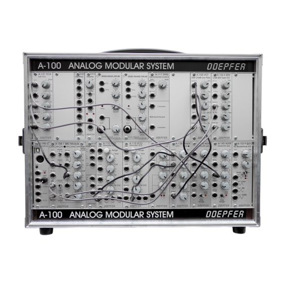
DOEPFER A-100 Series 매뉴얼 - 페이지 4
{카테고리_이름} DOEPFER A-100 Series에 대한 매뉴얼을 온라인으로 검색하거나 PDF를 다운로드하세요. DOEPFER A-100 Series 8 페이지. Analog modular system, connecting the breakout module to the main module
DOEPFER A-100 Series에 대해서도 마찬가지입니다: 사용 설명서 (8 페이지), 매뉴얼 (16 페이지), 사용자 설명서 (12 페이지), 조립 및 배선 매뉴얼 (6 페이지), 매뉴얼 (8 페이지), 매뉴얼 (6 페이지), 연결 (8 페이지)

A-105 / A-122
At close to maximum resonance, the filter starts to
self-oscillate, and behaves like a sine wave oscilla-
tor. Thanks to this effect, you can use the filter as an
independent tone source.
am plit ude
0 d b
Fig. 2:
How resonance affects the behaviour of a
low pass filter.
4
System A - 100
4. In / Outputs
! Audio In
This is the filter's audio input socket, where you
patch in the output from any sound source.
" FCV 1
Socket FCV 1 is a voltage control input for the filter.
re s onan ce
It works on the 1V / octave rule, like the VCOs.
If you connect the output of a modulation source (eg
LFO, ADSR) to this input, the cut-off frequency of the
filter will be modulated by its voltage: ie, the sound
color changes according to the voltage put out by the
modulator.
P
frequency
f
c
§ FCV 2
Socket § is also a voltage-control input for the filter.
Unlike on socket ", though, you can adjust the level of
voltage by using the attenuator 3 , and thus control the
intensity of modulation effect on the filter.
If you use this VCF as a sine wave oscillator,
connect a pitch control voltage to this input.
Do the same if you want the filter's cut-off
frequency to track exactly with the pitch of a
note.
doepfer
