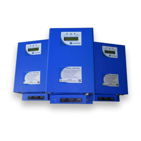
ASHAPOWER NEON-40 사용자 설명서 - 페이지 5
{카테고리_이름} ASHAPOWER NEON-40에 대한 사용자 설명서을 온라인으로 검색하거나 PDF를 다운로드하세요. ASHAPOWER NEON-40 14 페이지. Multi voltage range solar mppt charge controller

INSTALLATION & OPERATION
:
1.PV Panel Grouping
Using required Solar MC4 connectors and parallel connectors,
group the PV panel array according to the recommended grouping chart provided.
Good quality weather proof solar cables must be used.
:
2.Battery Bank Setup
If more than one battery is used, Connect the interlinking
cables (16 sq.mm minimum) tightly and check each battery separately for specific
gravity and backup.
3.MPPT Charge Controller Installation:
-
- Mount the MPPT charge controller vertically on the wall.
- Never keep any object on the device blocking the cooling fan.
- Avoid exposure to rain, direct sunlight or high temperature.
- Remove the terminal cover of the device and make sure the device is switched off.
- Connect the device to the battery bank using 16sq.mm/10Sq.mm standard cables.
- Connect the cables from PV panels to the solar terminals of the device with correct polarity.
- Switch ON the Power switch of the device.
-Three LED Indicators and cooling fan of the device starts functioning for 5 seconds and goes
off.Display shows the voltage of the connected battery bank and applicable range of PV
Panel Open Circuit Voltage (Voc) limit for the connected battery bank.Ensure the displayed
battery bank voltage and connected battery bank voltage are same when MPPT is powered
The Charger starts functioning when the PV Panel voltage detected is higher than
ON.
the connected battery bank voltage and green LED lights up. If the PV panel voltage
goes below the battery bank voltage the green indicator goes off. When the device
detects more than 2A charging current to the battery, RED LED lights up. If the
current is less than 2A the RED LED goes off. When the battery voltage reaches
14.0V(Configurable) the BLUE LED lights up and the phase input to the inverter
connected through the MPPT will be blocked. Now the load starts functioning on
inverter (Solar). When the solar charging current stops the load will be taken from
the battery bank and the battery voltage goes down. Once it reaches
11.0V(Configurable) the device change over the load from inverter to grid power and
the blue LED goes off. Blinking blue LED indicates Low battery bank voltageie.11.7V
(Configurable)giving warning to remove heavy loads.The blinking of green LED
indicates sharing of solar current for battery charging and connected load. Solar/Grid
status can also be monitored remotely by connecting an LED to the Solar/Grid
Monitor Port for a distance up to 30 meters with wire.
- Automatic Grid/Solar power Change Over :
If the Automatic Grid/Solar power Change
Connect the grid power phase wire (using
Over is required, follow the instructions below: -
4sq.mm/6sq.mm) to the 'Phase In' part of the terminal on the device. Connect
another wire from the 'Phase Out' part of the terminal to the input phase connector
of the inverter. (Never connect the neutral of the grid power to any terminal of the
charger. Refer Connection diagram provided).
4
