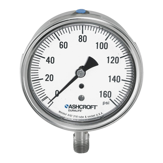
Ashcroft 1082 설치, 운영 및 유지보수 매뉴얼 - 페이지 7
{카테고리_이름} Ashcroft 1082에 대한 설치, 운영 및 유지보수 매뉴얼을 온라인으로 검색하거나 PDF를 다운로드하세요. Ashcroft 1082 20 페이지. Pressure gauge

also be drained from the case and the front ring
loosened before autoclaving.
3.0 INSTALLATION
3.1 Location – Whenever possible, gauges
should be located to minimize the effects of
vibration, extreme ambient temperatures and
moisture. Dry locations away from very high
thermal sources (ovens, boilers etc.) are pre-
ferred. If the mechanical vibration level is
extreme, the gauge should be remotely locat-
ed (usually on a wall) and connected to the
pressure source via flexible tubing.
3.2 Gauge reuse – ASME B40.1 recommends
that gauges not be moved indiscriminately
from one application to another. The cumula-
tive number of pressure cycles on an in-service
or previously used gauge is generally
unknown, so it is generally safer to install a
new gauge whenever and wherever possible.
This will also minimize the possibility of a
reaction with previous media.
3.3 Tightening of gauge – Torque should
never be applied to the gauge case. Instead,
an open end or adjustable wrench should
always be used on the wrench flats of the
gauge socket to tighten the gauge into the fit-
ting or pipe. NPT threads require the use of a
suitable thread sealant, such as pipe dope or
teflon tape, and must be tightened very
securely to ensure a leak tight seal.
CAUTION: Torque applied to a diaphragm
seal or its attached gauge, that tends to loosen
one relative to the other, can cause loss of fill
and subsequent inaccurate readings. Always
apply torque only to the wrench flats on the
lower seal housing when installing filled,
diaphragm seal assemblies or removing same
from process lines.
3.4 Process isolation – A shut-off valve
should be installed between the gauge and
the process in order to be able to isolate the
gauge for inspection or replacement without
shutting down the process.
3.5 Surface mounting – Also known as wall
mounting. Gauges should be kept free of piping
strains. The gauge case mounting feet, if applic-
able, will ensure clearance between the pres-
sure relieving back and the mounting surface.
3.6 Flush mounting – Also known as panel
mounting. The applicable panel mounting
cutout
dimensions
www.ashcroft.com
4.0 OPERATION
4.1 Frequency of inspection – This is quite
subjective and depends upon the severity of
the service and how critical the accuracy of
the indicated pressure is. For example, a
monthly inspection frequency may be in order
for critical, severe service applications.
Annual inspections, or even less frequent
schedules, are often employed in non-critical
applications.
4.2 In-service inspection – If the accuracy of
the gauge cannot be checked in place, the user
can at least look for (a) erratic or random
pointer motion; (b) readings that are suspect
– especially indications of pressure when the
user believes the true pressure is 0 psig. Any
gauge which is obviously not working or indi-
cating erroneously, should be immediately
valved-off or removed from service to avoid a
possible pressure boundary failure.
4.3 When to check accuracy – Obviously any
suspicious behavior of the gauge pointer war-
rants a full accuracy check be performed.
Even if the gauge is not showing any symp-
toms of abnormal performance, the user may
want to establish a frequency of bench type
inspection.
4.4 When to recalibrate – This depends on the
criticality of the application. If the accuracy of
a 3-2-3% commercial type gauge is only 0.5%
beyond specification, the user must decide
whether it's worth the time and expense to
bring the gauge back into specification.
Conversely if the accuracy of a 0.25% test
gauge is found to be 0.1% out of specification
then obviously the gauge should be recalibrat-
ed.
7
can
be
found
at
