Ashcroft F5504 설치 및 유지보수 지침 매뉴얼 - 페이지 4
{카테고리_이름} Ashcroft F5504에 대한 설치 및 유지보수 지침 매뉴얼을 온라인으로 검색하거나 PDF를 다운로드하세요. Ashcroft F5504 6 페이지. Differential pressure gauges

Installation and Maintenance Instructions for
F5504 Differential Pressure Gauges
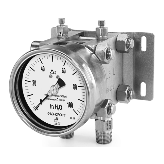
5.2 Description of function
The compared pressures are measured by flexible stainless
steel diaphragms on either side of the chamber. The two
diaphragms are mechanically linked by a rigid connecting rod.
To compensate high static pressures, the cavity between the
two diaphragms is filled with hydraulic fluid. When pressures
are equal on both diaphragms, they are at zero position.
When there is a difference in pressures acting on the two
diaphragms, they are deflected away from the high pressure
side, towards the lower pressure side, causing a displacement
of the connecting rod. A precision mechanism translates
the linear displacement of the diaphragm connecting rod to
angular movement of the gauge's dial pointer. The pointer's
displacement range of 270° corresponds to the full scale
differential pressure. The connecting rod has intermediate
flanges on either side, which protects the diaphragms against
excess differential pressure.
5.3 Description of components
5.3.1 Dial scale and pointer
The differential pressure gauge is equipped with a dial face and
pointer pursuant to DIN 16003, nominal size 100 mm or 160 mm.
5.3.2 Instrument connection
The instrument connection is located on the underside of the
differential pressure gauge and can be a threaded or flanged
similar to DIN EN 61518.
5.3.3 Vent and flushing connection
The vent and flushing connection of each pressure chamber is
located on its top side. It is closed by a screwed in G
5.4 Accessories
The use of a 3 or 5 valve manifold is highly reccomended.
Please contact Ashcroft or your Ashcroft representative
regarding available special tools and accessories.
© Ashcroft Inc. 2022, 250 East Main Street, Stratford, CT 06614-5145, USA, Tel: 203-378-8281, Fax: 203-385-0357, www.ashcroft.com
All sales subject to standard terms and conditions of sale. F5504_gauge_i&m_008-10299_RevA_05-02-22
¼ NPT
⁄
plug
1
8
6 TRANSPORT
6.1 Safety
The differential pressure gauge should be protected against
the effects of knocks and impacts. The device should only be
transported in the packaging provided, to protect against glass
breakage. The device should only be transported in a clean
condition (free of residues of measuring media)
6.2 Transport inspection
The delivery must be checked for completeness and damage
during transport. In the event of damage during transport, the
delivery must not be accepted, or only accepted subject to
reservation of the scope of the damage being recorded and, if
necessary, a complaint initiated
6.3 Storage
The differential pressure gauge must be stored in dry, clean
conditions, within a temperature range of -40 to 160°F (-40
to +70 °C), protected against direct exposure to sunlight and
protected against impact damage
7 ASSEMBLY/INSTALLATION
7.1 Safety
To ensure safe working during installation and servicing,
suitable shut-off valves must be installed (see 5.4 Accessories),
enabling the device:
• To be depressurized or taken out of operation;
• To be disconnected from the main pressure source for repair
or checks within the relevant plant;
• Or to enable function tests of the device to be performed "on
site".
During the mounting/installation of the gauge, the equipment
must be protected against the main pressure source and elec-
trical connections isolated from being switched back on.
7.2 Preparations (requirements for the installation location)
• A check on suitability of the device for the medium to be
measured, the scope of the measurement range and static
pressure and of the protection against special conditions
such as vibration, pulsation and pressure spikes.
• A bracket must be installed to support the pressure gauge if
the process pipe is not able to provide adequate support.
• The installation location should be chosen such that the
work-spaces for operating personnel are not located to the
rear of the pressure gauge.
7.3 Mounting/Installation
7.3.1 Process connection
The instrument is intended and factory adjusted for vertical
mounting, pressure ports downward. When mounted in other
orientation (max. ± 10°) the pointers' zero position needs to be
adjusted (see 7.4.1 Zero point adjustment).
• Connection to be undertaken by authorized and qualified
staff specialist only.
.
4
