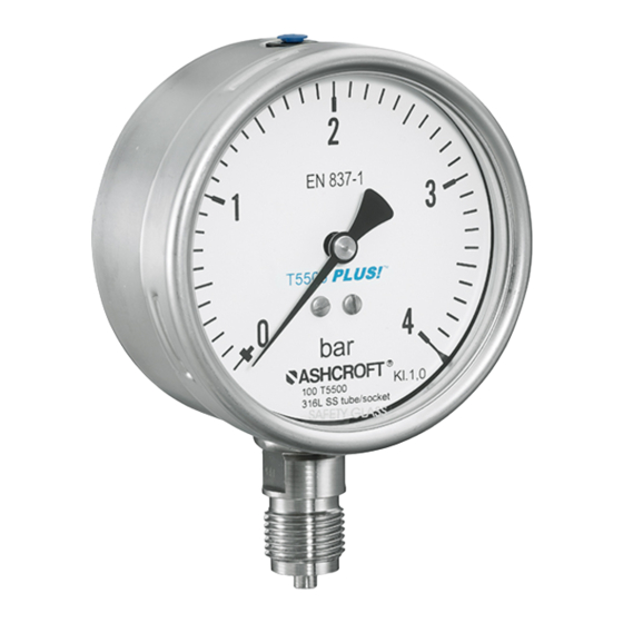
Ashcroft T6500 설치 및 유지 관리 지침 - 페이지 4
{카테고리_이름} Ashcroft T6500에 대한 설치 및 유지 관리 지침을 온라인으로 검색하거나 PDF를 다운로드하세요. Ashcroft T6500 5 페이지. Pressure gauges with switching contacts
Ashcroft T6500에 대해서도 마찬가지입니다: 설치 및 유지보수 지침 (6 페이지)

Installation and Maintenance Instructions for
T5500 and T6500 Pressure Gauges
pockets can form, and for measurements of gases no water
pockets. If the necessary incline is not achieved, then at
suitable points water separators or air separators must be
installed.
• The pressure metering pipe must be kept as short as possible
and laid without sharp bends, to avoid the occurrence of
irritating delays.
• With liquid measurement media, the pressurized connection
pipe must be degassed, since any gas bubble inclusions
result in measurement error.
• If water is used as the measurement medium, the device
must be frost-protected.
Safety notice: Only mount using the correct
open-jawed wrench, and do not twist the
device itself.
7.4 Starting up
The precondition for start-up is proper installation of all
electrical feed lines and metering pipes. All connecting lines
must be laid such that no mechanical forces can act on the
device. Before start-up, the seal on the pressurized connection
line must be checked.
7.4.1 Zero point adjustment
The pressure gauges are supplied calibrated ex works, so
that as a rule there is no need for calibration works at the
installation point. For devices with Micrometer pointer (see.
order code), zero point adjustment on site is possible. For this,
proceed as follows:
• Depressurize the pressure metering pipe.
• Check if internal pressure
was built up in the case
due to ambient temperature
effect. Open valve (position
B), wait for pressure relief
and close valve again
(position A)
• Open the bayonet ring and
remove ring and window.
• Hold the pointer in place
while turning the screw, until
the pointer (after releasing
again) has the correct
position.
• Close the case again and pay attention to correct fit of
window, gasket and bayonet ring.
Liquid filled gauges must be demounted
before the zero point adjustment can be done
(on a horizontal area to prevent leaking).
© Ashcroft Inc. 2018, 250 East Main Street, Stratford, CT 06614-5145, USA, Tel: 203-378-8281, Fax: 203-385-0357, www.ashcroft.com
All sales subject to standard terms and conditions of sale. T5500-6500_gauge_im_RevB_(008-10263)_01-02-19
7.4.2 Use under arctic condition
Pressure gauges with XQC option are designed for ambient
temperature range from -70 °C to 70°C. The vent valve must
be pulled out and open (position B). This vents the case to
atmospheric pressure and avoids wrong indication due to
pressure build up internally or pressure build up in the cause
that can induce fill leakage.
7.5 Subsequent relocation of the gauge (by the customer)
Recommendation: Do not remove the
pressure gauge from one metering point and
fit it in a different place, as there is a risk
of the measuring media being mixed, with
unforeseeable chemical reactions.
8 SERVICING
The device is maintenance-free. However, to ensure reliable
operation and a long lifetime for the device, we recommend
that it is checked regularly.
8.1 Safety
When undertaking servicing work on the device, the pressure
lines must be depressurized and the plant secured against
being switched on again.
8.2 Check on function, and recalibration
The check on function and recalibration is carried out at regular
intervals, depending on the application. The precise testing
cycles should be adjusted in line with the operating conditions
and ambient conditions. In the event of various device
components interacting, the operating instructions for all other
devices should also be taken into account.
• Check on display.
• Check on function, in conjunction with downstream
components.
• Check of pressurized connection pipes for seal condition.
8.3 Cleaning and maintenance
Cleaning is carried out using a non-aggressive cleaning agent,
with the ventilation valve closed and respecting the protection
category of the device.
9 FAULTS
9.1 Safety
Defective or faulty pressure gauges put the operational safety
and process safety of the plant at risk, and can lead to a risk or
injury to persons, the environment or the plant.
4
