DOLD BH 5911 사용 설명서 - 페이지 6
{카테고리_이름} DOLD BH 5911에 대한 사용 설명서을 온라인으로 검색하거나 PDF를 다운로드하세요. DOLD BH 5911 20 페이지. Multi-function safety system safemaster m control unit

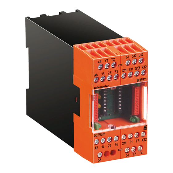
Indication
Green LEDs (left):
on, when all inputs are present and start
button activated.
Green LEDs (right):
on, when the safety outputs of the
control unit are activated.
White LEDs Run 1 and
Run 2 and semiconduc-
tor outputs 48 and 58:
Indicate the current status of the
control unit.
Setting of Functions
The control unit is assigned to the start inputs T1...T4 and the safety out-
puts via the DIP switches. The input function is set by means of the rotary
switches. To prevent accidently adjustments the setting switches are covered
by a front plate and are redundant.
The control unit is supplied with two fitted terminating connectors. When the
control unit is equipped with extension modules, remove these terminating
connectors and plug them to the last interconnected device. When a dia-
gnostic module is used, it is connected instead of the terminating con nector.
green LED "en 1"
0
2
3
4 output
S1
1
Mod3
9
7
8
Mod2
2
white LED
Mod1
3
"run 1"
4
Base
Mod3
5
white LED
"run 2"
Mod2
6
0 1
7
Mod1
2
Base
8
5
6
9
7
green LED "en 2"
on
off
base = Output of control unit
mod = Output of output module
Notes:
• Settings to the unit must be performed by skilled personnel while the
unit is disconnected.
• Before the front cover is removed, antistatic precautions must be
observed.
plate
green LED "K1"
start input
S2
1
T1
T2
2
T3
3
4
T4
T1
5
T2
6
7
T3
T4
8
green LED "K2"
Notes
• Settings to the unit must be performed by skilled personnel while
the unit is disconnected.
• Before the front cover is removed, antistatic precautions must be
observed.
Sw
Function
Start input selection
1 E-stop or 1 LC*
0
4 start inputs
2 channel
2 E-stop
1
4 start inputs
1 channel
1 E-stop or 1 LC*
3 start inputs
2
2 channel
3
not permitted (error 5)
1 E-stop or 1 LC*
4
4 start inputs
2 channel
2 E-stop
5
4 start inputs
1 channel
1 E-stop or 1 LC*
3 start inputs
6
2 channel
1 E-stop or 1 LC*
3 start inputs
7
2 channel
1 E-stop or 1 LC*
8
4 start inputs
2 channel
2 E-stop
9
4 start inputs
1 channel
* LC = light curtain
Automatic Start
Automatic start is only performed when the supply voltage is switched on
or when the Emergency stop or stop function has been reset (with switch
positions 7 to 9, also after undervoltage).
All other errors nevertheless require confirmation by a start input.
Manual Start
The start input must not be pressed for more than 3 seconds to start the
system. Alternatively, several start inputs may be assigned to one module.
Stop
Instead of the fourth start button, an additional stop input (NC contact)
can be connected. It is assigned only to the control unit and treated like an
additional single-channel emergency stop button.
This means that the safety outputs assigned to the control unit can only
be activated if neither the emergency stop or the stop button are activated.
If operating function 2, 6 or 7 is selected, an assignment to the start
input 4 will remain ineffective in all connected modules.
Lock-Out after Undervoltage
When an undervoltage is detected, the whole system (including any extension
modules) turns off (auto reset). There are two different options of auto restart:
1. The system de-energises the safety outputs as soon as undervoltage
has been detected.
There after the system will only reset after complete removal of voltage.
2. The system de-energises the safety outputs and remains de-energized until
supply voltage is back to a permissible value. Then, the system is restarted.
Shortcircuit and Crossfault Detection
The control unit has an integrated dynamic shortcircuit and crossfault
detection. This feature can only be used when the inputs are switched by
contacts and if they are only connected to one safemaster input.
To connect light curtains of type 4 or to operate several safemaster M
units from common sensors a special wiring has to be chosen.
6
Start function s
etting conditions
Automatic start
lock-out following
undervoltage
1 Stop
Manual start
1 Stop
Automatic start
1 Stop
following undervoltage,
restart after the voltage
has returned to the
permissible value
BH 5911 / 151007 / 478
