CYP CHDBT-1H2CE 운영 매뉴얼 - 페이지 9
{카테고리_이름} CYP CHDBT-1H2CE에 대한 운영 매뉴얼을 온라인으로 검색하거나 PDF를 다운로드하세요. CYP CHDBT-1H2CE 16 페이지. 1×3 hdmi over hdmi and cat5e/6/7 splitter with poe and lan serving
CYP CHDBT-1H2CE에 대해서도 마찬가지입니다: 운영 매뉴얼 (16 페이지)
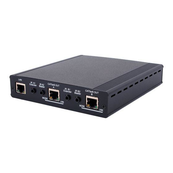
6.2 Rear Panel
LAN
1
1
LAN: Connect to an active network for LAN serving. When any
compatible LAN equipped receivers are connected, this allows
the network access (including internet access if available) to
be shared between any connected LAN equipped receivers.
Connect any Ethernet equipped device e.g. a Smart TV or games
console to the LAN port of a receiver for that device to share the
network/internet access.
Warning: DO NOT connect the LAN connection to the CAT5e/6/7
port. Doing so may cause a power shutdown and may damage
the device.
2
IR A1/B1 IR Extender: Connect the IR extenders for IR signal
reception . Ensure that the remote being used is within the direct
line-of-sight of the IR extender.
3
IR A2/B2 IR Blaster: Connect to the IR blasters for IR signal
transmission. Place the IR blaster in direct line-of-sight of the
equipment to be controlled. Use the supplied IR 'Y' Cable to ensure
control from each HDBaseT zone.
4
CAT5e/6 OUT A/B: Connect to HDMI to CAT5e/6/7 receivers (with
or without PoE function) with CAT5e/6/7 cable to extend the signal
up to 100m.
MODE LED: When the device is powered the LED will flash.
LINK LED: When the device is powered on and this slot is
connected to a compatible receiver device with CAT5e/6/7 cable
the LED will illuminate.
2
3
C
A
T
IR A1
IR A2
Extender
Blaster
MODE
2
5
e
6 /
O
U
T
IR B1
A
Extender
LINK
4
3
C
A
T
5
e
6 /
O
U
T
IR B2
B
Blaster
4