DOLD MINISTART GF 9016 원본 지침 번역 - 페이지 3
{카테고리_이름} DOLD MINISTART GF 9016에 대한 원본 지침 번역을 온라인으로 검색하거나 PDF를 다운로드하세요. DOLD MINISTART GF 9016 4 페이지. Softstarter and softstop device
Technical Data
General Data
Temperature range:
Operation:
Storage:
Relative air humidity:
Altitude:
Power reduction
At > 45°C:
For instal. heights over 1.000 m:
Overvoltage caregory /
polluiton degree:
Insulation class:
Main circuit:
Control and auxiliary circuit:
EMC
Interference resistance
Electrostatic discharge (ESD):
HF-irradiation
80 MHz ... 1.0 GHz:
1.0 GHz ... 2.5 GHz:
2.5 GHz ... 2.7 GHz:
Fast transients:
Surge voltage
between
wires for power supply:
between wire and ground:
HF-wire guided:
Voltage dips:
Interference emission
Wire guided:
Radio irradiation:
Degree of Protection:
Wire connection
Load terminals:
Stranded wire:
Control terminals:
Fixing torque:
Mounting:
Weight:
Dimensions
Width x height x depth (incl. terminals)
7.5 / 11 / 15 kW:
22 kW:
Standard Type
GF 9016 3 AC 400 V 50/60 Hz 7.5 kW
• Nominal voltage:
• Nominal motor power:
• Width:
Ordering Example
GF 9016
3 AC 400 V
50/60 Hz
0 ... + 45 °C
- 25 ... + 70°C
< 95%, no condensation at 40°C
< 1,000 m
- 2 % up to max. 60 °C
- 2 % 100 m each
III / 2
6 kV
2.5 kV
8 kV (air)
IEC/EN 61000-4-2
10 V / m
IEC/EN 61000-4-3
3 V / m
IEC/EN 61000-4-3
1 V / m
IEC/EN 61000-4-3
2 kV
IEC/EN 61000-4-4
1 kV
IEC/EN 61000-4-5
2 kV
IEC/EN 61000-4-5
10 V
IEC/EN 61000-4-6
IEC/EN 61000-4-11
Limit value class B
IEC/EN 60947-4-2
Limit value class B
IEC/EN 60947-4-2
IP 20
Plug in screw terminal
6
6
16
16
1.5 mm
2
cage clamp terminals
1.2 ...
1.2 ...
1.5 ...
1.5 ...
1.5
1.5
1.7
1.7
DIN-rail mounting
IEC/EN 60715
1.0
1.0
1.0
1.0
45 x 173 x 158 mm
52.5 x 178 x 158 mm
3 AC 400 V
7.5 kW
45 mm
7.5 kW
AC 230 V
Auxiliary supply
(only necessary > 500 V)
Nominal motor power
Nominal frequency
Nominal voltage
Type
Control Input
Connect conact to X1, X2 and select softstart (close contact) or softstop
(open contact). As option the unit can also be started by an external
control voltage of DC 10-24 V. This has to be connected to terminals X2,
X3, X4 connecting means starting up,disconnection stopping. On terminal
X3 a kickstart function can be activated. This is useful on motors that have
a high starting load as e.g. mills, breakers, conveyors. Kickstart takes 0.5
sec at fully switched thyristors.
Indicator Outputs
X5, X6: Error at phase failure, frequency variation, thyristor failure,
overtemperature of the unit, disconnected motor. Reset by
switching the unit off and on.
X7, X8: Softstart finished, semiconductors bridged.
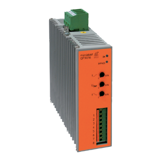
Adjustment Facilities
Potentiometer
U
start
t
t
Set-up Procedure
Set potentiometer "U
start
Set potentiometer "t " to maximum (fully clockwise).
Set potentiometer "t " to mid position.
Start the motor and turn potentiometer "U
turn without excessive humming.
Stop the motor and restart.
Adjust potentiometer "t " to give the desired ramp time.
Stop and restart the motor.
Adjust potentiometer "t " to give the desired deceleration time.
Stop and restart the motor, readjusting the potentiometers until the desi-
red starting/stopping characteristics are achieved.
mm
2
- Attention: If the ramp-up time is adjusted to short, the internal bridging
contact closes before the motor is on full speed.
This may damage the bridging contactor or bridging relay.
Nm
Safety Notes
kg
- Never clear a fault when the device is switched on
- Attention: This device can be started by potential-free contact, while
connected directly to the mains without contactor (see
application example). Please note, that even if the motor is
at rest, it is not physically separated from the mains.
Because of this the motor must be disconnected from the
mains via the corresponding manual motor starter.
- The user must ensure that the device and the necessary components
are mounted and connected according to the locally applicable
regulations and technical standards.
- Adjustments may only be carried out by qualified specialist staff and
the applicable safety rules must be observed.
3
Description
Initial setting
Starting voltage
fully anti-clockwise
Ramp-up time
fully clockwise
Deceleration time
fully clockwise
" to minimum (fully anti-clockwise).
" up until the motor starts to
start
11.01.21 en / 335A