Ashly ne1600.70 운영 매뉴얼 - 페이지 5
{카테고리_이름} Ashly ne1600.70에 대한 운영 매뉴얼을 온라인으로 검색하거나 PDF를 다운로드하세요. Ashly ne1600.70 16 페이지. Network enabled two channel power amplifiers
Ashly ne1600.70에 대해서도 마찬가지입니다: 운영 매뉴얼 (12 페이지), 운영 매뉴얼 (12 페이지)

Operating Manual - NE Two Channel Power Amplifiers
Protection
This amplifier come standard with several protection circuits:
Over Current Protection - Is controlled in the output stage.
Thermal Protection - The amplifier senses output device temperature and adjusts a two-speed fan to keep the operating
temperature within acceptable limits. If device temperatures exceed that limit, the input to that channel is first reduced, and as
a last resort the power supply will be switched off while the fan continues to run.
Mains Protections – protection within the power supply includes: Inrush Current Limitation during power up, Mains
Over Voltage Detection, and internal Mains Fuse Protection. To protect the Mains fuse against AC overcurrent due to excessive
audio output current, there is a protection scheme controlled in software and indicated on the amplifier front panel which reduces
audio output level until the overcurrent condition is no longer present.
Physical Description
Each model in the NE two channel series is 2RU, and weighs 22 pounds (10kg) or less. The model number is indicated
in the lower left corner of the front panel.
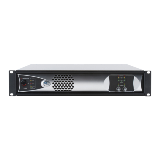
Amplifier Front Panel
1. Mounting Holes – For rack mounting.
2. Power Switch – Switches the unit on or off. Note: The power switch can be disabled from software.
3. Status LEDs – Indicate status of: Power, Standby, Protect, Power Switch Disable, and Com (Ethernet activity).
4. Air Vents – Cool air enters the sides and is blown out the front.
6. Signal LEDs – The lowest LED will begin to light when the output voltage reaches -18dBu below rated output. The
Clip LEDs will begin to flash when output voltage is 1/2 Volt below the output power supply voltage.
7. Bridge – This LED indicates that the two channels are selected to BRIDGE mode from the back panel switch, and that
only channel 1 level control is active.
8. Temp and Current LEDs – The Temp LED indicates that the amplifier has reached an excessively high operating
temperature. The Current LED confirms that the amplifier output is delivered to a speaker load.
9. Channel Attenuators – These control the input signal level to the amplifier section, and can be disabled from software.
10. Factory Reset – To reset internal configurations back to their original factory settings, including all device presets
and user passwords, press and hold this recessed front panel tact switch during power up until all channel LEDs are lit. Upon
reset completion, the LEDs will turn off and the amp will be in normal operating mode.
5
