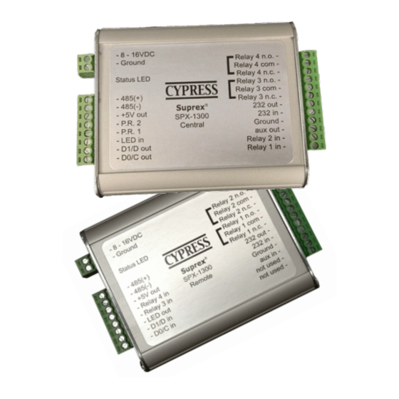
Cypress Suprex SPX-1300 운영 매뉴얼 - 페이지 7
{카테고리_이름} Cypress Suprex SPX-1300에 대한 운영 매뉴얼을 온라인으로 검색하거나 PDF를 다운로드하세요. Cypress Suprex SPX-1300 17 페이지. Reader extender
Cypress Suprex SPX-1300에 대해서도 마찬가지입니다: 운영 매뉴얼 (16 페이지)

Format setup and Remote Side Basic Reader Connections
2. Remove power from the units and set DIP switches if necessary. The units are set for Wiegand format data as
the default setting from the factory. If a Wiegand format reader is being used, it should not be necessary to change
the DIP switch setting.
For applications that require a change in the DIP switch setting. Remove the board from the enclosure and set the
DIP switch to the required format on both the Central and Remote units.
Refer to DIP switch diagram for the list of available formats.
3. Connect the Reader to the Remote unit. 2 different standard applications are shown as examples below.
Note: The LED and Door Strike operation of the SPX-1300 differs from previous versions.
The connection and operation is covered in the next 2 pages.
8 - 16 VDC
Power
Supply
Wiegand Card
Reader
DC Power In
Ground
LED In
Data 1
Data 0
8 - 16 VDC
Power
Supply
Wiegand Card
Reader
DC Power In
Ground
LED In
Data 1
Data 0
Suprex Operation and Initial Setup
485 to
Central
Wiegand Reader with 5 Volt power supplied by Suprex
485 to
Central
Wiegand Reader with 8-16 Volt power Connections
2-8 to 16 VDC In
1-Ground
8-485(+)
7-485(-)
Remote Unit
6-+5 VDC Out
5-RLY4 Input (5V)
*
4-RLY3 Input (5V)
3-LED Output
2-D1/Data/F2F Input
1-D0/CLK Input
2-8 to 16 VDC In
1-Ground
Remote Unit
8-485(+)
7-485(-)
6-+5 VDC Out
5-RLY4 Input (5V)
*
4-RLY3 Input (5V)
3-LED Output
2-D1/Data/F2F Input
1-D0/CLK Input
12-RLY2 N.O.
11-RLY2 Com
10-RLY2 N.C.
9-RLY1 N.O.
8-RLY1 Com
7-RLY1 N.C.
6-RS232 Out
5-RS232 In
4-Ground
3-Aux In
2-N/C
1-N/C
12-RLY2 N.O.
11-RLY2 Com
10-RLY2 N.C.
9-RLY1 N.O.
8-RLY1 Com
7-RLY1 N.C.
6-RS232 Out
5-RS232 In
4-Ground
3-Aux In
2-N/C
1-N/C
