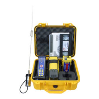
ACR Electronics VECTA 2 제품 지원 매뉴얼 - 페이지 6
{카테고리_이름} ACR Electronics VECTA 2에 대한 제품 지원 매뉴얼을 온라인으로 검색하거나 PDF를 다운로드하세요. ACR Electronics VECTA 2 13 페이지. Dual scale direction finder

2.0
INSTALLATION
2.1
Remote Omni-Directional Antenna (Rooftop, Pole, etc...)
The Vecta
is supplied with a specially designed and tuned 3' whip antenna (121.5 MHz) and
2
should be mounted as high as practical for optimum receiver range. Use a standard 1" x 14 thread
VHF style mount appropriate for your mounting location. Route the Coax to where the Vecta
mounted and connect via the external antenna jack. When the Vecta
the Omni-Directional antenna should be plugged in to achieve optimum performance while in the
"Monitoring" mode. When a signal has been detected, remove the Vecta
disconnect the Omni-Directional Antenna and deploy the antenna blades for "Search" mode. While
the antenna looks and mounts like a standard 3' VHF marine antenna, it is not. Do not attempt to
use the Vecta
with any other antenna. This action will damage the Vecta
2
warranty.
Figure 3
3.0
OPERATION
3.1
Holding the Vecta
Turn the unit ON, (if used for training, switch to
Train mode) hold the Vecta
away from your body, in a vertical orientation
and at ear level. Holding the Vecta
manner also polarizes the antenna with a
vertically
oriented
improves the ability to hear signals in the early
stages of a search by positioning the Vecta
speaker next to your ear.
The right-hand front antenna element of the Vecta
body's effect on the front to back ratio of the antenna is minimized when in this position.
2.2
Folding Handle / Mounting Bracket
The Vecta
is supplied with a folding handle that also functions as part of
2
the mounting bracket. This handle allows the Vecta
while searching and also be secured to a fixed bracket when not in use
or is just monitoring. To mount the bracket, select a flat location allowing
for the antenna and power wires to be routed. Before drilling holes and
screwing down the bracket, test fit the Vecta
able to slide in and out of the bracket unobstructed. It is not necessary
to deploy the antenna blades while the unit is in its bracket and attached
to the remote Omni-Directional antenna.
2
in the left hand
2
in this
2
BEACON
antenna
and
2
™ is the electrically active element and the
2
5
is in its mounting bracket,
2
from its bracket,
2
and may void the
2
to be hand held
2
making sure the unit is
2
Figure 4
Y1-03-0227 Rev. A2
is
2
