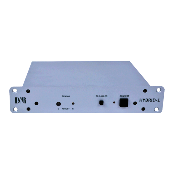
D&R HYBRID-1 사용자 설명서 - 페이지 4
{카테고리_이름} D&R HYBRID-1에 대한 사용자 설명서을 온라인으로 검색하거나 PDF를 다운로드하세요. D&R HYBRID-1 13 페이지. Interface between professional audio equipment and the public telephone network
D&R HYBRID-1에 대해서도 마찬가지입니다: 사용자 설명서 (17 페이지)

USER MANUAL
The D&R Telephone Hybrid-1 is designed to create an easy connection between the public telephone line and your
studio equipment.
The Hybrid has to be inserted between your telephone and the telephone line. Connect the two wires of the tel-
ephone line's wall unit to the RJ-11 connector labelled LINE (wall) and connect the telephone appliance itself to the
Hybrid's phone output on the RJ-11 connector labelled PHONE. This can be done with standard available cable as-
semblies from your local phone shop.
Now the Hybrid is interfaced (fully balanced) between your telephone appliance and its connection to the outside
world. The hybrid can now split the send and return signals.
Now connect the hybrid's balanced audio input labelled TO CLEANFEED OUTPUT to a (preferable) balanced output
of around +4dBu. This output has to be the mix of all signals except the signal coming from the hybrid itself to avoid
feedback.
An Aux. output on your mixer will do as well as long as you keep the Aux. send of the channel you return the phone
signal on closed (all other Aux. sends need to be open), or in broadcast mixers a clean-feed is the best.
The Hybrid-1 stereo jack connector labelled TO MIC INPUT has to be connected to a Mic level input of your mixing
console.
NOTE: The output of the Hybrid has to be connected to a Mic input of the mixing console, because the outgoing
level is very low because of the passive circuitry inside the Hybrid.
WIRING SCHEME
PHONE
LINE (wall)
TO MIC INPUT
TO CLEANFEED OUTPUT
______________________________________________________________________________________________
WIRING OF BOTH PHONE AND LINE RJ-11 CONNECTORS
PHONE/WALL RJ-11
Pin 1:
Pin 2
Pin 3
Pin 4
______________________________________________________________________________________________
WIRING OF AUDIO IN AND OUTPUTS
STEREO JACK TO MIC INPUT
Screen
Tip
Ring
______________________________________________________________________________________________
STEREO JACK TO Clean feed output FUNCTION
Screen
Tip
Ring
______________________________________________________________________________________________
: RJ-11 connector to connect with a handset.
: RJ-11 connector to connect with the public telephone network.
: Stereo jack output to be connected to mic input of the mixer.
: Stereo jack input to be connected to Mix Minus/Clean feed (N-1)output of the mixer.
FUNCTION
n.c.
A (telephone line)
B (telephone line)
n.c.
FUNCTION
Screen (ground)
Phase (hot)
Non-phase (cold)
Screen (ground)
Phase (hot)
Non-phase (cold)
CONNECTION
In/out
In/out
CONNECTION
Audio ground
Audio +
Audio -
CONNECTION
Audio ground
Audio +
Audio -
page-4
