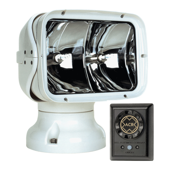
ACR Electronics RCL-75 제품 지원 매뉴얼 - 페이지 6
{카테고리_이름} ACR Electronics RCL-75에 대한 제품 지원 매뉴얼을 온라인으로 검색하거나 PDF를 다운로드하세요. ACR Electronics RCL-75 20 페이지. Remote control searchlight system
ACR Electronics RCL-75에 대해서도 마찬가지입니다: 제품 지원 매뉴얼 (15 페이지), 제품 지원 매뉴얼 (20 페이지)

Tools and fasteners needed for installation
The following tools and marine-grade fasteners are needed for
installation but are not included in the light kit.
4 each, 1/4" dia. bolts
4 each, Lock nuts
4 each,Washers
1 each, 1/4" Drill bit for bolt
holes
1 each, 15/16" Drill bit for cable clearance
1 each, 13/64" Drill bit for remote switch mounting bolts
1 each, Tube of silicone or bedding compound to close hole around
cable
OPTION: 1-inch mounting riser shapeable for irregular surfaces (P/N
9427, see Figure 6).
WARNING: Be careful when using electrical power tools around
water. Follow manufacturer's instructions. Electric shock could occur.
Location Selection
Care and consideration should be given to the selection of a mounting
location for the RCL-75 and the Point Pad™ (remote control panel).
Location helps assure maximum performance of the light.
Typical mounting locations include bow pulpit, fore deck, and cabin
hardtop (see Figures 2 and 3).
CAUTION: Do not mount the searchlight upside down.
The mounting surface should be flat and parallel to the water's surface.
Keep in mind that the further the light is from the pulpit, the greater the
chance that light will reflect off the boat and into the operator's vision.
Before installing the light or remote control switch, find a suitable path
for the wires to run. There are two sets of wires: (a) a 17-foot (5.18
meter) wiring harness, which will connect the light and the remote Point
Pad™, and (b) power leads which will connect the light to a power
source. A path will be needed for both. Wire should be kept from contact
with sharp edges, and tight radii. If wire needs to pass through a
Y1-03-0158G
OR 4 each, 1/4" dia.
Lag screws
OR 1 each, 17/64" Drill
bit for lag screws
5
