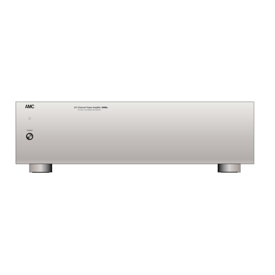
AMC 2445a Instructions For Installation And Operation Manual - Page 6
Browse online or download pdf Instructions For Installation And Operation Manual for Amplifier AMC 2445a. AMC 2445a 13 pages. 2/4 channel power amplifier
Also for AMC 2445a: Specification Sheet (2 pages)

1. AC LINE CORD.
Plag the AC line cord into a nearby wall
outlet that provides the correct AC power
line voltage, or into a convenience outlet on
any AMC product.
2. 2CH/4CH "MODE" SWITCHES.
There are two slide switches on the back
panel labelled "2CH 4CH". These switches
allow the 2445/2445a to opreated in
several modes depending on the number
of loudspeakers to be connected. These
modes of operation are defined as follows;-
2 CHANNEL MODE.
the 2CH. position, the 2445/2445a
becomes a two channel (stereo) amplifier
capable of driving two 8 ohm loudspeakers
at 90 watts per channel. In this mode, the
2445/2445a can be used as a high power,
audiophile quality, stereo power amplifier.
CAUTION: In the 2CH. mode, the speaker
terminals should be directly wired to the
loudspeaker and not to any accessory
device like headphones adaptors etc. That
may share a common ground with other
channels.
4 CHANNEL MODE.
the 4CH. position, the 2445/2445a
becomes a four channel amplifier capable
of driving four 4 ohm loudspeakers at
greater than 45 watts per channel. In this
mode, the 2445/2445a can be used for
Dolby surround sound systems and multi-
room type applications.
3. INPUTS.
There are four RCA photo connectors on
the back panel that connect to the inputs of
each of the four power amplifiers.
Connections to these inputs are made with
reference to the MODE SWITCH settings
described above;-
2 CHANNEL MODE.
left channel input can be made via CH3
RCA input connector and for the right
channel input, use the input connector of
CH1.
NOTE: In this mode, the input photo
With both switches in
With both switches in
Connections for the
connectors of CH2 and CH4 are
disconnected.
4 CHANNEL MODE.
2445/2445a opreates as a 4 channel
amplifier. Connections to the inputs of
these amplifiers are made through the RCA
phono connectors of CH1 through 4.
4. INPUT LEVEL CONTROLS.
Each channel of the 2445/2445a has its
own, independant level control. Before
turning on the 2445/2445a for the first time,
make sure that all level controls are set to
their fully clockwise position. These
controls can be used for various functions.
For example, they can be used to match
the levels of loudspeakers in a multi-room
installation, or to lower the sensitivity of the
power amplifier, so that the volume control
on the pre-amplifier is at a more convenient
and usable position. They can also be used
to optimise the balance in a stereo system.
NOTE: In the 2 channel mode, only the
input levelcontrols of CH1 and CH3 are
operative. The controls for CH2 and CH4
are switched out of circuit.
5. CONVENIENCE AC OUTLETS.
There are 2 switched AC outlets and one
unswitched outlet on the back panel of
120V versions of the 2445/2445a. For
220V/230V/240V version. there is only one
unswitched AC outlet. These outlets can be
used to provide AC power for other audio or
video components.
6. LOUDSPEAKERS TERMINALS
The 2445/2445a is equipped with binding
post type speaker terminals that are
designed to handle the extremely high
peak currents that this amplifier is capable
of giving. Connections from these
terminals to the loudspeakers should be
made with heavy-duty wire. Stranded wire
of 16 gaugeor thicker is recommended
especially if low impedance loudspeakers
are used. The following describes the
connections for 2 channel and 4 channel
In this mode, the
