AMC XG Instructions For Installation And Operation Manual - Page 8
Browse online or download pdf Instructions For Installation And Operation Manual for Amplifier AMC XG. AMC XG 13 pages. 16 channel

TRIGGER.
When the remote power
switch is set in the TRIGGER position,
the
AMC
XG
automatically by an external trigger
voltage. The trigger voltage is applied to
the trigger input socket, located on the
back panel of the XG.. This trigger
voltage can originate from a system
controller or from another XG. The
sensitivity of this input ranges from +3V
DC/AC to +30V DC/AC. The current
required from the trigger source is only
0.2mA.
The XG is also provided with a trigger
output socket, also located on the back
panel. When the XG is turned on, the
trigger output socket provides a +12Vdc
Signal that can be looped through or
"daisy-chained" to the trigger input of
another
XG
amplifier
component)
in
installation. When the external trigger
voltage is set to 0V, the XG will be in
standby mode and the voltage from the
trigger output socket will likewise be 0V.
CONSTANT.
When the remote power
switch is set in the CONSTANT position,
the power on and off states of the AMC
XG are controlled by the front panel
master power on/off switch.
NOTE: The bi-color power LED above the
front panel power switch, indicates the
power status of the XG. This LED will
light up RED when the XG is in stand-by
mode and GREEN when turned on.
10. 12V DC OUT & 3~30V DC/AC IN
When the remote power switch is set in
the TRIGGER position, the AMC XG can
be turned on automatically by an external
trigger voltage. The trigger voltage is
applied to the "3~30V DC/AC IN" trigger
input socket. This trigger voltage can
originate from a system controller or from
can
be
turned
(or
other
a
multi
component
another XG. The sensitivity of this input
ranges from +3V DC/AC to +30V DC/AC.
on
The current required from the trigger
source is only 0.2mA.
When the XG is turned on, the "12V DC
OUT" trigger output socket provides a
+12Vdc Signal that can be looped
through or "daisy-chained" to the trigger
input of another XG amplifier (or other
component)
installation. When the external voltage is
set to 0V, the XG will be in standby mode
and the voltage from the trigger output
socket will likewise be 0V.
11. FUSE
There is T5AL 250V fuse put inside the
fuse holder besides AC Inlet. Replace
always with the same type of fuse.
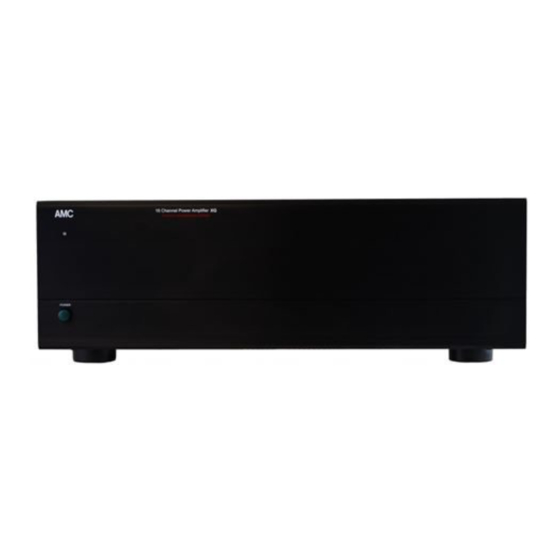
FRONT PANEL.
1.POWER
INDICATOR.
The press button switch marked power
can be used to switched the XG on or off.
When the XG is switched on, the led
above the power switch will light up.
6
in
a
multi
component
SWITCH
AND
POWER
