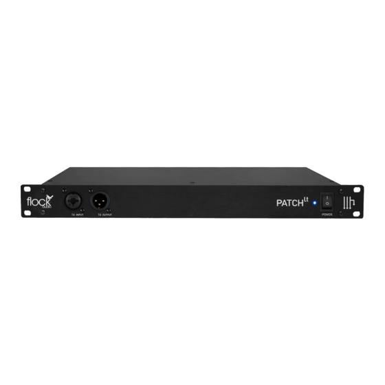
Flock Audio PATCH LT Quick Setup Diagram
Browse online or download pdf Quick Setup Diagram for Recording Equipment Flock Audio PATCH LT. Flock Audio PATCH LT 2 pages. Setting up your patch model for the first time
Also for Flock Audio PATCH LT: Connecting (7 pages), User Manual (20 pages)

QUICK SETUP DIAGRAM
SETTING UP YOUR PATCH MODEL FOR THE FIRST TIME
1176 Compressor
(Rear Connections)
Input
Note: Physical Connection Signal Flow
All Physical Cable Connections must be properly connected in
order to confirm proper signal flow and functionality of the
PATCH System.
For Example:
PATCH (Outputs)
—>
External Hardware (Inputs)
External Hardware (Outputs)
—>
PATCH (Inputs)
INPUTS & OUTPUTS NOTICE
INPUTS & OUTPUTS ON THE REAR PANEL OF THE PATCH SYSTEM ARE
SEPARATELY DESIGNATED. YOU CANNOT USE AN OUTPUT AS AN
INPUT OR VICE VERSA. PLEASE ENSURE TO AVOID RISK OR DAMAGE
TO THE PATCH SYSTEM OR OTHER EXTERNAL HARDWARE THAT IS
CONNECTED THAT YOU MAKE THE PROPER CONNECTIONS
ACCORDINGLY.
Output
Recording Interface
(Rear Connections)
www.flockaudio.com
Pultec EQ
(Rear Connections)
Output
Input
PATCH System
(Rear Connections)
Preamp
(Rear Connections)
Input
Output
(OPTIONAL) dB BOOSTER
DYNAMIC MICROPHONES
Inputs
Outputs
The PATCH Series models are all a +4 Professional Line Level Design. When
connecting Microphones directly to the PATCH Series Hardware, Standard Audio
Engineering Practices should be exercised such as the understanding that mixing
Signal Levels may or may not exhibit audio level &/or electronic noise floor artifacts.
If undesired results are experienced when connecting Microphones directly to the
PATCH Series, it is recommend to have a dB Booster or Transparent Preamp
between the Microphone and PATCH Model Connection (I.E. Mic -> Pre/dB
Booster -> PATCH) to achieve the best possible audio signal levels for routing.
See Next Page for PATCH APP
Hardware Setup Menu Labelling
@flockaudio
Microphone
