Flomatic CA501 Operation & Maintenance Manual - Page 3
Browse online or download pdf Operation & Maintenance Manual for Control Unit Flomatic CA501. Flomatic CA501 4 pages. Automatic control valve
Automatic Control Valve
Operation & Maintenance Manual
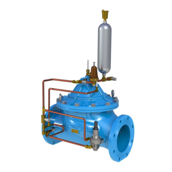
Model C501/CA501 Surge Arrestor Valve
4. Open ¼" Test Cock (9) at top of valve. Re-close when water runs clear and absent of air bubbles. It
may take several cycles to bleed the Surge Arrestor power chamber properly.
5. Open the main line shut off valve (Gate or Butterfly valve) at the inlet (High Pressure) side of the
surge arrestor valve fully. If there is a main line shut-off valve at the outlet side of the surge arrestor
valve, open slowly. Water will flow through the open valve initially and decrease as the valve closes
gradually.
6. The controls of the Surge Arrestor Valve have been factory preset in accordance with the specified
operating conditions as provided on order placement. However, minor field adjustments may be
required as follows:
1. With pump running and developing the maximum pumping pressure:
a. If the Surge Arrestor Valve is open and passing water, turn the adjusting screw of
b. If the Surge Arrestor Valve is closed, turn the adjusting screw of the Over Pressure
2. Shut down the pump and observe the pressure at which Under Pressure Pilot (5) starts to
open the Surge Arrestor Valve. To increase under pressure setting, turn the adjusting screw
of the Under Pressure Pilot (5) clockwise. To decrease under pressure setting, turn the
adjusting screw of the Under Pressure Pilot (5) counter-clockwise.
OPERATION:
The over pressure pilot is a Normally Closed Model BPP Back Pressure Sustaining Pilot that remains closed
when system pressure is below the pilot set point. The under pressure pilot is a Normally Open Model PRR
Pressure Reducing Pilot that remains closed when the system pressure is above the pilot set point.
When the Model PRR Pressure Reducing Pilot (under pressure pilot), senses a subnormal pressure created by
the low-pressure portion of the surge wave (immediately after pump shut down or power failure), it causes the
main valve to open rapidly by exhausting control water from above the diaphragm of the main valve to an
accumulator. This insures that the main valve is open in anticipation of the returning high-pressure portion of the
surge wave to eliminate potential shock or hammer. When system pressure recovers within the normal
operating pressure zone above the Model PRR under pressure pilot set point, the main valve closes slowly at a
rate controlled by an adjustable flow control valve to prevent valve closing surges, and the accumulator will drain
in preparation for the next cycle.
When the Model BPP Back Pressure Sustaining Pilot (over pressure pilot), senses high pressure equal to or
above it's set point, it causes the main valve to open rapidly by exhausting control water from above the
diaphragm of the main valve. When system pressure recovers within the normal operating pressure zone below
the Model BPP over pressure pilot set point, the main valve closes slowly at a rate controlled by an adjustable
flow control valve to prevent valve closing surges.
15 Pruyn's Island Drive
Glens Falls, New York 12801
Phone: (800) 833-2040
the Over Pressure Pilot (4) clockwise slowly until the main valve closes. Lock the
adjusting screw in this position.
Pilot (4) counter-clockwise slowly until the valve opens and passes water; then
clockwise as noted in (a) above.
WWW.FLOMATIC.COM
High Quality Valves Built to Last...
MANUAL: C501 REV: 4