Flomec QS200 Installation Manual
Browse online or download pdf Installation Manual for Measuring Instruments Flomec QS200. Flomec QS200 8 pages. Insertion ultrasonic flowmeter options for large pipe sizes
Also for Flomec QS200: Product Owners Manual (16 pages), Product Owners Manual (20 pages)
INSTALLATION GUIDE
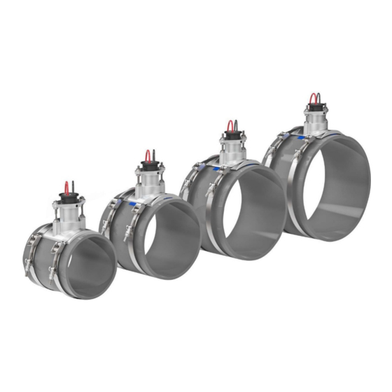
The FLOMEC QS200 provides a robust ultrasonic
flowmeter for irrigation applications. The QS200 uses
Percentage of Reading (RD) Accuracy which is superior to
an impeller flow sensor/flowmeter that uses Percentage
of Full Scale (FS) Accuracy
ACCURACY WHITE PAPER for more information on RD and
FS information @
http://bit.ly/flomec-accuracy-wp). Also,
the QS200 does not have any moving wetted parts, so
there is no need to replace damaged parts.
IMPORTANT:
Read the General Safety Instructions for this flowmeter (see last page) before beginning any installation procedures.
GENERAL INSTALLATION PROCEDURE
The following lengths of straight pipe should be connected to the QS200 FLOMEC Tee (or NON-FLOMEC Tee):
10 times the pipe's inner diameter upstream of the meter
-
5 times the pipe's inner diameter downstream of the meter
-
The pipe needs to be full of irrigation water with no air inside. Built-up sediment on the QS200's transducers or large
debris can greatly hinder the meter's performance. Keep the following in mind when installing:
Install QS200 at an angle as shown in Figure 1a.
-
1 inch pipe installations will need a larger angle
-
of 45 degrees.
Flow direction arrows on the QS200 insert must
-
match flow direction of water through the pipe
(see Figure 1a).
FLOMEC Tee is bidirectional for flow (the QS200
-
insert IS NOT bidirectional - the flow direction
matters).
Flow direction of the QS200 should be horizontal
-
or upward. DO NOT install flowmeter in a
downward flow direction, to avoid partially filled
pipes (see Figure 1b).
FLOMEC
(download the FLOWMETER
QS200
®
This meter uses a two-wire system that is connected to an
irrigation controller's flow sensor input (or decoder's flow
sensor port) and meets the cable distance recommended
by Irrigation controller/decoder manufacturers. The
two-wire system communicates via a square wave pulse
that is converted to flow rate at the controller (identical
to an impeller flow sensor communicating to irrigation
controller/decoder). The QS200's power is supplied
through these same two wires by the controller's/
decoder's flow sensor input/port
(voltage range of 7.5 V
When installing below ground, install meter in a
-
valve box with a thick layer of gravel below the
meter.
DO NOT direct bury QS200 flowmeter.
-
If using a Non-FLOMEC Tee, verify the QS200
-
insert physically fits into the Non-FLOMEC Tee.
DO NOT pull on the QS200 wires under any
-
circumstances.
Confirm that the Controller/Decoder flow sensor
-
input (or port) will supply the QS200 two-wire
meter with the appropriate power
(7.5 V
to 36 V
DC
-1-
to 36 V
).
DC
DC
).
DC
08/20 IND-1126 Rev A QS200 Installation Guide