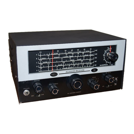
Ameco R-5 Owner's Manual - Page 6
Browse online or download pdf Owner's Manual for Receiver Ameco R-5. Ameco R-5 17 pages.

AC line voltage – 117 volts.
Signal generator with 50 ohm output impedance.
Modulated 30% at 400 Hz.
0.1 uF in series with signal generator for DC isolation.
Output measured across 3.2 ohm resistor connected to PHONES jack with AC voltmeter.
1.0 volt RMS reference output.
AGC disabled by shorting terminals 2 and 3 on S 102A.
Oscillator disabled by shorting front section of main tuning capacitor, C 102B.
VOLUME at maximum
ANL switch OFF
BAND on E
RF GAIN at maximum
AM-CW switch on AM.
APPROXIMATE µ V INPUT:
10
400
22
1,000
55
600
400
0.9 V
32,000
GLOSSARY OF TERMS
AM – Amplitude Modulation
ANL – Automatic Noise Limiter
ANT – Antenna
AVC – Automatic Volume Control. Also, called AGC – Automatic Gain Control
BFO – Beat Frequency Oscillator
6
INPUT TO:
Q 1 Base
With C 113 disconnected from bandswitch.
Q 1 Collector
Q 2 Emitter
Q 2 Collector
Q 4 Base
Short T3, terminals 4 & 5
Q 4 Collector
Short T3, terminals 4 & 5
Q 5 Emitter
Short T3, terminals 4 & 5
Q 5 Collector
RF GAIN at Minimum
CR 3 Cathode
RF GAIN at Minimum
NOTES:
"
"
"
