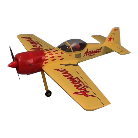
aero-naut Sukhoi SU 31M Building Instructions - Page 4
Browse online or download pdf Building Instructions for Toy aero-naut Sukhoi SU 31M. aero-naut Sukhoi SU 31M 6 pages. Electric rc model aircraft

Canopy
Don't cut out the canopy frame (25) yet.
Cut out the instrument panel from the decal sheet and apply it to the front of the canopy frame (25).
The pilot's backrest can be painted a different colour if you wish. Cut out the canopy (26) leaving a
flange about 20 mm wide. Glue the canopy to the canopy frame. When the glue has set hard trim the
joined canopy parts leaving a flange 10 mm wide at the canopy recess. Glue the plywood support (27)
to the underside of the canopy frame (25). Bend a hook (49) at right-angles and glue it in place,
centred on the support (27); this hook must be set at right-angles to the fuselage centreline.
Tension a rubber band (53) from each of the two hooks (49) (in the front of the fuselage) to the rear
hook in the fuselage. When the canopy is fitted the two rubber bands are then engaged in the hook on
the bottom of the canopy.
Wing
Lay the two wing panels (29 + 29) upside down on a flat surface. Fit the carbon tube wing spar (30)
into both wing panels from the centre and glue all three parts together (Fig. 21). Apply the film strips
(56) to the top surface of the wing to act as hinge reinforcements; half the width (25 mm) should be on
the wing, half on the aileron. Before gluing the servos in the wing set them to neutral from the
transmitter (Fig. 22). The servo leads have to be extended as described in the RC system operating
instructions. The wing ribs are already cut away to clear the servo leads. At the centre section a hole
must be cut through the high-density foam in the direction of the centre of the wing, so that the servo
leads exit the wing on the top surface.
Glue the balsa supports (52) in the slots in both ailerons. Please take care that no glue gets onto the
aileron hinge. The spigot of the aileron horns (34) has to be shortened slightly; roughen the joint
surfaces and file notches in the spigot to provide a "key" for the epoxy. Glue the horns in the balsa
supports (52) (Fig. 22). The ailerons can now be cut through at the inboard end to separate them from
the wing (Fig. 24). To check the aileron system connect the pushrods (35) to the servo output arms
and the aileron horns, and secure them with the retainer clips (59) (Fig. 23). Aileron travel should be
30 mm to each side of neutral. When you are satisfied, remove the pushrods (35) again and glue the
servos in place. Position the bottom wing fairing (31) in the recess in the wing, and push the servo
output arms through the foam material. Remove the fairing and enlarge the slots slightly so that the
output arms and aileron pushrods have proper clearance when they move. The fairing (31) can now
be glued to the underside of the wing. This is best carried out in two stages: first glue the front edge
(behind the leading edge) and allow the glue to set hard, then glue the remainder of the fairing in
place. On the underside of the wing glue the four circular balsa reinforcements (60) for the nylon
screws (42) in the recesses designed for them.
Centre of Gravity
The model should balance at a point 85 mm aft of the wing root leading edge, measured directly
adjacent to the fuselage. Adjust the position of the flight battery to obtain correct balance.
Decals
Cut out the individual decals and apply them to the model in the arrangement shown in the kit box
illustration.
Control surface travels
Elevator:
20 mm each side
Rudder:
50 mm each side
Ailerons:
30 mm each side
Building instructions - Sukhoi SU 31M
Sukhoi SU 31M
4
