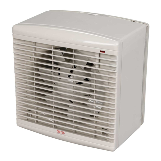
Domus Ventilation DX6PR Installation And Maintenance Manual - Page 2
Browse online or download pdf Installation And Maintenance Manual for Fan Domus Ventilation DX6PR. Domus Ventilation DX6PR 7 pages. Flat roof fan kit 50hz/60hz

Installation and Maintenance
DX Flat Roof Fan Kit 50Hz/60Hz
3.0 General Dimensions
3.0 General Dimensions
DX Unit
DX Unit
A
A
6"
6"
269
269
9"
9"
337
337
12"
12"
413
413
*minimum height of Flat roof upstand (by others).
*minimum height of Flat roof upstand (by others).
4.0 Flat Roof Kit Installation
4.0 Flat Roof Kit Installation
Prepare a timber or builders work upstand on the roof to the
Prepare a timber or builders work upstand on the roof to the
dimensions below. Carry roof felt or weathering material over the curb
dimensions below. Carry roof felt or weathering material over the curb
to ensure a good seal. The kit is supplied with the fan, spacer and grille
to ensure a good seal. The kit is supplied with the fan, spacer and grille
assembled for transit purposes.
assembled for transit purposes.
The instructions opposite assume the fan assembly has been separated
The instructions opposite assume the fan assembly has been separated
to begin the installation.
to begin the installation.
Fan Code
Fan Code
A
A
DX6FR
DX6FR
610
610
DX9FR
DX9FR
610
610
DX12FR
DX12FR
695
695
Figure 2. Flat roof upstand construction details.
Figure 2. Flat roof upstand construction details.
A x B overall finished curb size
A x B overall finished curb size
150mm min.
150mm min.
C x D ceiling opening
Figure 3. Exploded assembly Flat Roof Kit.
Figure 3. Exploded assembly Flat Roof Kit.
Roof
Terminal
Fan / Terminal
Fan / Terminal
fixings (4)
fixings (4)
Grille
Grille
fixings
fixings
(2)
(2)
LAB1347R May 2018
B
B
C*
C*
161
161
150
150
170
158
158
150
150
180
172
172
150
150
185
B
B
C
C
610
610
300
300
300
610
610
450
450
450
695
695
450
450
450
Roof felt/
Lead flashing
Roof slab
Ceiling panel
C x D ceiling opening
Roof
Terminal/
Terminal/
Terminal
Upstand
Upstand
fixings (4)
fixings (4)
Upstand
Spacer
Spacer
Fan unit
Fan unit
Fan / Spacer
Fan / Spacer
fixings (4)
fixings (4)
Internal
Internal
Grille
Grille
1
1
D
D
170
Drill through the
Drill through the
dimples in the Roof
dimples in the Roof
180
Terminal.
Terminal.
185
2
2
Position centrally &
Position centrally &
squarely over curb and
squarely over curb and
fix using 6mm wood
fix using 6mm wood
screws and sealing
screws and sealing
washers.
washers.
D
D
300
3
3
450
450
Feed the supply cable
Feed the supply cable
through the spacer.
through the spacer.
4
4
Roof felt/
Offer up the spacer
Offer up the spacer
Lead flashing
section to the terminal
section to the terminal
underside and fix using
underside and fix using
Roof slab
the 4, 5mm screws
the 4, 5mm screws
provided.
provided.
Ceiling panel
5
5
Release the electrical cover
Release the electrical cover
from the fan plate.
from the fan plate.
6
6
Assemble the fan
Assemble the fan
to the spacer
to the spacer
Upstand
section 4 panhead
section 4 panhead
screws.
screws.
7
7
Fit the grille to
Fit the grille to
the fan, locating
the fan, locating
top lip before
top lip before
fixing.
fixing.
V E N T I L A T I O N
Spacer
Spacer
For various wiring options
For various wiring options
see wiring details page 4.
see wiring details page 4.
2
2
Page 2
