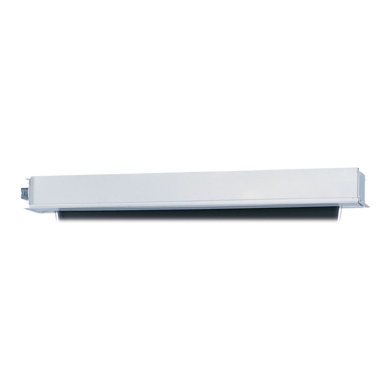
Da-Lite Large advantage electrol Instruction Book - Page 3
Browse online or download pdf Instruction Book for Projection Screen Da-Lite Large advantage electrol. Da-Lite Large advantage electrol 12 pages. Installer friendly features
Also for Da-Lite Large advantage electrol: Instruction Book (12 pages), Installer's Manual (2 pages), Instruction Book (13 pages)

sCreeN ANd roller AsseMBlY iNsTAllATioN
Tools required for screen and roller assembly:
9/16" Open Wrench
or Socket Driver
If your screen was shipped with the motor and roller already installed proceed to step 7.
1. Remove the access door. First, remove the 2 bolts from each
end with a 9/16" open wrench or socket driver. Next, use a
5/32" hex key to remove the two screws in the center of the
access door. This will allow the door to drop open on the hinges
(Figure 1).
2. Carefully unpack screen and roller assembly. Leave packing
paper on the roller.
3. Remove the square peg bracket from the motor end of the
roller assembly (Figure 2).
4. Remove the safety clip from the motor attachement bracket
located in the motor end of the screen housing.
5. Use a 1/2" open wrench or socket driver to loosen the four bolts
that secure pin end mounting bracket into housing. Lift pin end
of roller into position and slide the bracket into the roller pin.
Tighten all four bolts. Slide the pin end bracket towards the end
of the case (Figure 3).
6. Place the roller assembly into the case with the motor on the
left side. The limit switches should be facing down. Line up the
head of the motor with the motor attachment bracket.
Bolts
Figure 1
1/2" Open Wrench
or Socket Driver
Door Support Screws
Access Door
Screen Motor
5/32" Hex Key
7. Complete electrical hook-up by snapping motor 1/3 wire
connectors into case connectors (Figure 2).
8. Return to motor end and insert safety clip over casting bracket
to secure motor end.
9. Carefully remove tape strips securing picture surface around
roller. Slat should move freely. (Only if the roller assembly is pre
installed.)
Caution! Do not Cut tape on fabriC with a knife
or any sharp tool. remoVe by hanD.
10. Test installation by running screen up and down a few times.
Be prepared to stop screen should any objects obstruct the
movement of the screen. To prevent damage to the motor, the
standard duty cycle is 1 minute on and 3 minutes off.
11. Re-install the access door. Procedure is the reverse of step 1
listed above.
LVC Control Box
Screen Motor
Limit Switches
Figure 2
Bolts
Bolts
Figure 3
3
