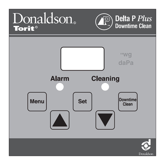
Donaldson Torit Delta P Plus Installation And Operation Manual - Page 10
Browse online or download pdf Installation And Operation Manual for Controller Donaldson Torit Delta P Plus. Donaldson Torit Delta P Plus 16 pages.

- 1. Table of Contents
- 2. Description
- 3. Operation
- 4. Inspection on Arrival
- 5. Electrical Wiring
- 6. Installation
- 7. Setpoint Adjustment
- 7. Quick Start Instructions
- 7. Adjustments
- 7. Password Protected Settings
- 8. Delta P Plus Control Calibration
- 9. Optional Settings
- 10. Troubleshooting
- 11. Replacement Parts
Donaldson Company, Inc.
Optional Settings
See Printed Circuit Board illustration.
230 VAC Power Supply
To operate at 230 VAC, remove two jumpers labeled W1
and W3. Reinsert one of the jumpers in position W2.
Change from English to Metric (SI) Units
1. Turn power to the Delta P Plus Control ON.
2. Use the Menu key to select PAS.
3. Press SET, then use the arrow keys to display "4",
press SET again.
4. Press the MENU key repeatedly until you reach P 6.
5. Press SET, then use the arrow keys to display "0",
press SET again.
6. After 10 seconds with no further button action, the
display will return to reading the pressure.
Disable Setpoint Adjustment
To restrict setpoint changes, install a jumper wire across
the PROG. DISABLE terminals (3 & 4) on Terminal Block
2, TB2. The current settings will still be displayed, but
no changes can be made until the jumper is removed.
Interrupting the jumper with a key-operated, normally-
closed switch installed in the enclosure door provides
temporary access to the setting functions without
opening the door.
External Alarm Reset / Disable (TB2,
Terminal 5 & 6)
If desired, wire the ARM RESET terminals (5 & 6) on
Terminal Block 2, TB2, to a key-operated, normally-open
switch. Closing the switch turns the alarm OFF.
7
Internal Alarm Disable (J5)
To disable the alarm internally, remove the jumper on
MODE Jumper Block J5, located on the lower-right
quadrant of the circuit board. Disabling the alarm relay
reduces the alarm function to the ALARM LED visual
display only.
Hi/Lo Control (TB3, Terminals 7, 8, & 9)
Per the wiring diagram supplied with the controller, the
Hi/Lo terminals are connected to the pressure switch
input on the timer board. In most cases this connection
is made at the factory.
Terminal 8 is common, terminal 7 is normally open, and
terminal 9 is normally closed.
Auxiliary Relay Output (TB3, Terminals 10,
11, & 12)
1. If the jumper on the MODE Jumper Block J5 is not
installed, the auxiliary relay output will not function.
2. If the jumper is installed in the ALARM mode
position, the auxiliary relay output activates based on
the setting of the ALARM setpoint.
3. If the jumper is installed in the SLAVE mode position,
the auxiliary relay output activates in parallel with
the HI/LO CONTROL relay.
Terminal 11 is common, terminal 10 is normally open, and
terminal 12 is normally closed.
Analog Output (TB4, Terminals 13 & 14)
Terminals 13 & 14 on Terminal Block 4, TB4, in the
upper-left quadrant of the circuit board, provide a 4 to
20 mA output proportional to the 0-to-maximum span
of the pressure sensor. This circuit requires a 500 ohm
maximum load.
