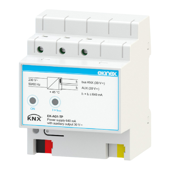
Ekinex EK-AG1-TP Quick Start Manual - Page 2
Browse online or download pdf Quick Start Manual for Controller Ekinex EK-AG1-TP. Ekinex EK-AG1-TP 3 pages. Bus power supply 640 ma with auxiliary output 30 vdc

• the maximum distance between two bus devices can-
not exceed 700 m;
• the maximum length of a bus line is 1000 m, keeping into
account all segments.
At the same bus line can be connected not more than two
power supplies. A second power supply may be necessa-
ry when the installation in distribution boards requires a
particular concentration of the bus devices (tipically more
than 30 units installed within 10 m). In this case a po-
wer supply has to be installed near the group of devices.
Between two power supplies installed on the same bus
line a minimum distance of 200 m is required, measured
along the line.
!
Warning! In order to supply the KNX bus lines use
only KNX bus power supplies (e.g. ekinex EK-AB1-
TP or EK-AG1-TP). The use of other power supplies
can compromise the communication and damage
the devices connected to the bus.
Mounting
The device has degree of protection IP20, and is the-
refore suitable for use in dry interior rooms. The hou-
sing is made for rail mounting according to EN 60715
in boards or cabinets for electrical distribution. The
installation is in horizontal position, the correct posi-
tion is when the terminals for KNX bus line and auxi-
liary output are located at the bottom and the terminals
(
, L, N) for connecting the mains power supply 230 Vac
are located at the top. For the installation of the device on
the rail proceed as follows:
• with the aid of a tool bring the locking device in the fully
lowered position (1);
• place the upper edge of the rear inner profile on the
upper edge of the rail (2);
• rotate the device towards the rail (3);
• push the locking device upward until it stops (4).
Before removing the device, be sure the bus terminals
have been extracted from their slots. Use a screwdriver
to slide down the locking device and remove the device
from the rail.
1
3
i
Note. When mounting the device in boards and ca-
binets it shall be provided the necessary ventilation
so that the temperature can be kept within the ope-
rating range of the device.
Electrical connections
Main supply 230 Vac
The connection to the 230 main supply Vac is made with
screw terminals ( , L, N) located on the upper front of the
device. Characteristics of the terminal blocks:
2
4
• screw clamping of conductors
• maximum cross section of conductor 2.5 mm²
• recommended wire stripping approx. 6 mm
• torque max 0.5 Nm
L
230Vac
N
50/60Hz
PE
+
KNX
-
+
AUX
30Vdc
-
KNX bus line
The connection to the KNX bus line is made with the ter-
minal block (black/red) included in delivery and inserted
into the slot located on the bottom left part of the front.
Characteristics of the KNX terminal block:
• spring clamping of conductors
• 4 seats for conductors for each polarity
• terminal suitable for KNX bus cable with single-wire
conductors and diameter between 0.6 and 0.8 mm
• recommended wire stripping approx. 5 mm
• color codification: red = + (positive) bus conductor,
black = - (negative) bus conductor
Auxiliary output
The auxiliary output 30 Vdc is provided with a dedicated
terminal block (yellow/white) included in the delivery and
inserted into the slot located on the bottom right part of
the front. The terminal block for the auxiliary output has a
color codification different than that for the connection of
the KNX bus. Characteristics of the terminal block:
• spring clamping of conductors
• 4 seats for conductors for each polarity
• terminal suitable for KNX bus cable with single-wire
conductors and diameter between 0.6 and 0.8 mm
• recommended wire stripping approx. 5 mm
• color codification: yellow = + (positive) AUX conductor,
white = - (negative) AUX conductor
To connect the auxiliary output to the powered devices it
is recommended to use a cable with a sheath of different
color than that used to connect the KNX bus line.
2
