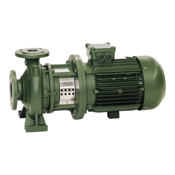
DAB NKM-G 100-400 Instruction For Installation And Maintenance - Page 9
Browse online or download pdf Instruction For Installation And Maintenance for Water Pump DAB NKM-G 100-400. DAB NKM-G 100-400 20 pages.

10.2.
STOPPING
Close the interception device on the delivery pipe. If there is a check device on the delivery pipe, the interception valve on the
delivery side may remain open as long as there is back pressure downstream from the pipe.
If hot water is to be pumped, arrange that the pump can be stopped only after having excluded the source of heat and let sufficient
time elapse to allow the liquid temperature to drop to acceptable values, so as not to create excessive temperature increases inside
the pump body.
For a long period of inactivity, close the interception device on the intake pipe and, if supplied, all the auxiliary control connections.
To guarantee maximum system functionality it will be necessary to arrange for brief running periods (5 - 10 min) at intervals of 1 to
3 months.
If the pump is removed from the system and stored, proceed as indicated in par.5.1
11.
PRECAUTIONS
11.1.
The electropump should not be started an excessive number of times in one hour. The maximum admissible value is as follows:
THREE-PHASE MOTORS UP TO AND INCLUDING 4 kW
THREE-PHASE MOTORS OVER 4 kW
11.2.
DANGER OF FROST: When the pump remains inactive for a long time at temperatures of less than 0°C, the pump body must be
completely emptied through the drain cap, to prevent possible cracking of the hydraulic components.
Check that the leakage of liquid does not damage persons or things, especially in plants that use hot water.
Do not close the drainage cap until the pump is to be used again.
When restarting after long periods of inactivity it is necessary to repeat the operations described above in the paragraphs
"WARNINGS" and "STARTING UP".
11.3.
To avoid needless motor overloads, accurately check that the density of the pumped liquid corresponds to that used in the design
phase: remember that the power absorbed by the pump increases in proportion to the density of the liquid carried.
12.
MAINTENANCE AND CLEANING
The electropump can only be dismantled by competent skilled personnel, in possession of the qualifications
required by the legislation in force. In any case, all repair and maintenance jobs must be carried out only after
having disconnected the pump from the power mains. Ensure that it cannot be switched on accidentally.
If the liquid has to be drained to carry out maintenance, ensure that the liquid coming out cannot harm persons or
things, especially in systems using hot water. The legal requirements on the disposal of any harmful fluids must
also be complied with. After a long period of operation there may be difficulties in removing the parts in contact
with water: to do this, use a special solvent available on the market and, where possible, use a suitable extractor.
Do not force the parts with unsuitable tools.
12.1.
Periodic checks
In normal operation, the pump does not require any kind of maintenance. However, from time to time it is advisable to check current
absorption, the manometric head with the aperture closed and the maximum flow rate, which will enable you to have advance warning
of any faults or wear. If possible, arrange for programmed maintenance so that problem-free operation may be ensured with minimum
expense and reduced machine down times, thus avoiding long and costly repairs.
12.2.
Shaft seal
12.2.1. Mechanical seal
Normally no checking is required. Just ensure that there are no leaks of any kind. If leaks are present, change the seal as described
in par.12.3.1
12.3.
Greasing the bearings
Carry out maintenance based on the type of bearing indicated on the technical data plate.
See tables on page 105 (12.3.1)
12.4.
Changing the seal
12.4.1. Preparing disassembly
1. Switch off the electric power supply and ensure that it cannot be switched on accidentally.
2. Close the interception devices on intake and delivery.
3. If hot liquids have been pumped, wait until the pump body returns to room temperature.
4. Empty the pump body by means of the drainage caps, taking particular care if harmful fluids have been pumped (observe the
legal requirements in force).
5. Dismantle any auxiliary connections provided.
12.4.2. Changing the mechanical seal
Slacken the nuts from the stud bolts in order to slip the pump body off the motor block. Preventing shaft rotation by mmobilising the
shaft itself or the impeller, slacken the nut; remove the flat washer and the spring washer. Slip off the impeller, if necessary levering
with two screwdrivers on the lantern cover. Then remove the tab. Retain the spacer or spacers; extract the mechanical seal. To
facilitate extraction, lever with two screwdrivers on the seal spring, taking care not to spoil the seat of the seal. NB: extraction may
be facilitated by lubricating the shaft with alcohol.
Before assembly, ensure that the seat of the seal has not been scored; if it has, eliminate the scores with abrasive cloth. If that is not
sufficient, replace the coupling.
Reassemble proceeding in inverse order and ensuring particularly that:
– the fittings of the individual parts must be free from residue and spread with suitable lubricants;
– all the O-Rings must be perfectly whole. If not, replace them.
TYPE OF PUMP
ENGLISH
MAXIMUM NUMBER OF STARTS PER HOUR
20
100
20
