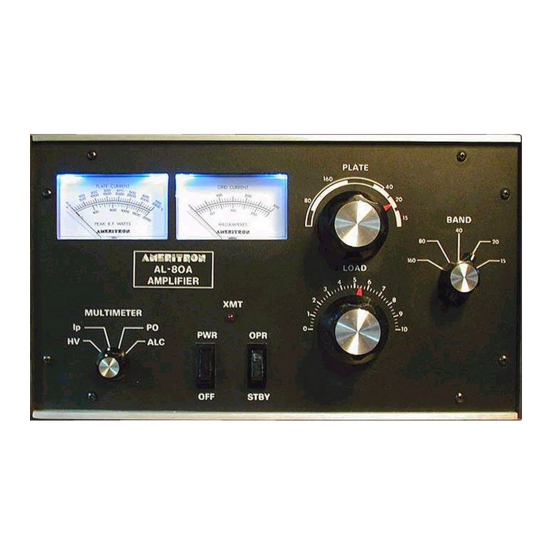
AMERITRON AL-80A Instruction Manual - Page 5
Browse online or download pdf Instruction Manual for Amplifier AMERITRON AL-80A. AMERITRON AL-80A 6 pages. High power linear amplifier
Also for AMERITRON AL-80A: Instruction Manual (13 pages), Instruction Manual (7 pages), Instruction Manual (12 pages)

7. Key
the exciter (no drive) and
observe
the plate current on the 0-700
mA
scale. Plate current should
now
read
.
between
50 mA and 100 mA.
.
I
8. Apply only enough
drive to indicate a grid current of 50 mA
or an Ip of no more
than 200
mA.
Tune
the PLATE",
/r-'
control for maximum
grid current. Itis normal
for the plate current to dip at this point. Ifthe grid current goes
over
100 mA
reduce
the drive at once.
Unkey
the exciter.
9. Place the MUL TIMETER
switch inthe PO positionand observe the 0-2000 peak RF. watts scale.Apply the same
drive again and adjust the LOAD
and PLATE
controls for maximum
output on the 0-2000 scale.
10. Increase the drive until 125mA of grid current is indicated. Adjust the LOAD and PLATE controls again for max-
imum output. The grid current will be lower now.
11. Advance the drive to 200 mA of grid current. Adjust the LOAD and PLATE controls for maximum output power.
(Repeat this step twice.) The output should be around 1000-watts now with 100 watts of exciter power.
12. Apply enough drive to indicate either 1000 watts of output power or 200 mA of grid current. Re-peak the LOAD
and PLATE controls. The grid current must not be over 200 mA, the plate current over 550mA or the output over
1200 watts.
13. In CW operation the drive power should be reduced until the plate current is 400 mA or
less.'F6r"5S~
operation
the modulation crest should not exceed 400 mA plate current, 100 mA grid current or 1200 watts PEP output.
The AL-80A will operate with full output on all WARC bands except 24.5 MHz. The
AL-80AX (export model) will operate with full output on all WARC bands.
STANDARD FREQUENCY COVERAGE
4
,
TUNING
CHART (Typical)
FREQUENCY
BANDSWITCH
PLATE CONTROL
LOAD CONTROL
1.85
160
160
4
3.5
80
80
1
3.8
80
80
3
7.2
40
40
5
14.2
20
20
5
21.2
15
15
7
';c
24
.
5
10
20
7
*28.7
10
15
8
.:: A L-80AX
(export
model)
AL-80A
AL-80AX
160 meters
1.8-2.0 MHz
160 meters
1.8-2.0 MHz
80 meters
3.3-4.4 MHz
80 meters
3.3-4.4 MHz
40 meters
6.3-8.3 MHz
40 meters
6.3-8.3 MHz
20 meters
9.5-15.5 MHz
20 meters
9.5-15.5 MHz
15 meters
15.5-21.5 MHz
15 meters
15.5-21.5 MHz
10 meters
24-29 MHz
