DoorHan CV01 Owner's Manual - Page 9
Browse online or download pdf Owner's Manual for Control Unit DoorHan CV01. DoorHan CV01 12 pages.
Also for DoorHan CV01: Installation And Operation Manual (4 pages), Manual (8 pages)
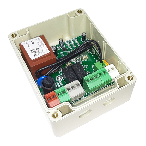
Fig. 3. Connection of electrical lock
Terminal
(N, L) XP3
N
L
Motor (M-L2, M-L1, M-N) XP5
M-N
M-L1
M-L2
XP2 control unit
Open
Close
GND
XP6
XP1
5. PROGRAMMING
5.1. CONTROL UNIT OPERATING MODES
1. Standby mode. Connecting the control unit to the mains puts the device in the standby mode where it remains until a control
command is given from a remote control or a key-switch; or until switching to programming mode.
220V
Transformer
220 × 12, 15 W
220V, 50 Hz
AC 12 V
Function
Connection of the AC supply voltage, 220 V/50–60 Hz
Power (neutral)
Power (line)
Electrical motor connection
Common drive wire (blue wire)
Direction of the drive movement — open (black wire)
Direction of the drive movement — close (brown wire)
Switch connection
Opening
Closing
Ground
Connection of the control contacts of an external receiver or a key-button
Output of constant unstabilized voltage, +12 V
Electrical lock
Table 3. Control board terminals (fig. 1, 2, 3)
PROGRAMMING
9