Astrapool E25 Installation And Operating Instructions Manual - Page 3
Browse online or download pdf Installation And Operating Instructions Manual for Water Filtration Systems Astrapool E25. Astrapool E25 10 pages. Salt chlorinator

- 1. Operating Instructions
- 2. Table of Contents
- 3. General Overview
- 4. Chlorinator Control Installation
- 5. Cell Installation
- 6. Pool Preparation
- 7. Programming
- 8. Chlorine Output
- 9. Setting the Right Chlorine Output and Filtration Time
- 10. Chlorinator Maintenance and Troubleshooting
- 11. Maintenance of Your Chlorinator
- 12. Troubleshooting
- 13. Warranty
GENERAL OVERVIEW
Congratulations! You have purchased an AstralPool E- SERIES Salt Chlorinator. Please read the instructions carefully and
your purchase will provide you with years of trouble free use.
Your AstralPool Chlorinator works by converting some of the salt (sodium chloride) in your pool into chlorine which starts to
destroy algae and bacteria and sanitises your pool. As part of the process, the chlorine is converted back into salt and hence
salt is not consumed.
Your Chlorinator control has many features which ensure simple operation of your chlorinator and Filtration system.
The E-SERIES Chlorinator has an internal electronic time clock designed to operate the Filtration pump up to 2 separate
time periods each day. The control has a non replaceable backup power source which is designed to maintain timer setting
memory in the event of an infrequent and short power interruption.
WARNING: This appliance is not intended for use by persons including young children or infirm persons with reduced
physical, sensory or mental capabilities, or lack of experience or knowledge, unless they have been given supervision
or instruction concerning use of the appliance by a person responsible for their safety.
Please ensure that young children are supervised to ensure that they do not play with the pump or chlorinator.
To avoid a safety hazard, the supply cord if damaged, must only be replaced by AstralPool, or its service agent or a suitably
qualified person.
CHLORINATOR CONTROL INSTALLATION
The E-SERIES Chlorinator control has a Rating of IP23 enabling it to be installed outdoors. Regulations require that the
control is not allowed to be located within 3.5 metres of the pool water.
The Chlorinator Control should be installed in a well ventilated position ideally away from direct sunlight. Ensure that the
unit is not located near pool chemicals as fumes may damage the control.
When installing the control on a post, first attach a flat waterproof panel at least 300mm wide by 500mm long. Make sure
the control is located centrally on the panel and sits flat.
Plug the 3 pin plug into a suitable weatherproof outlet and then plug the pump into the 3 pin socket in the Chlorinator
control.
Note: The pump current rating must not exceed 8 amps.
CELL INSTALLATION
The Chlorinator Cell must be located last in the pipe work just prior to the return to the pool. If valves are installed between
the Chlorinator and the pool outlet, it is essential that they cannot deadhead the pump. If the pressure in the cell exceeds
250kPa and/or the water temperature exceeds 40 degrees Celsius, the cell may fail.
WARNING: Never install the cell before the pump or heater
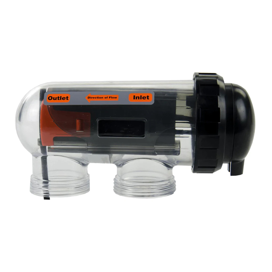
The Cell MUST be installed with the barrel unions underneath (water connections pointing downwards) and the cell should
be horizontal. 50mm fittings have been provided. Use 50mm (2") high pressure PVC pipe and glue into the 50mm barrel
union tails. Make sure that the 'O-rings are correctly fitted and the unions are tightened firmly.
Direction of flow through the Cell is critical – unit must be plumbed with the water entering the cell at the end closest
to the terminal connections (as indicated by flow direction label mounted on cell)
INST 363 E Series Salt Chlorinator V05.17
3
