Dor-O-Matic 1993 Installation Instructions Manual - Page 8
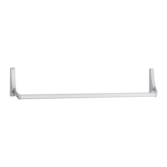
Browse online or download pdf Installation Instructions Manual for Safety Equipment Dor-O-Matic 1993. Dor-O-Matic 1993 8 pages. Concealed vertical rod panic device

Hinge Stile
1/8"
7/16"
See note
F
Face of
door stop
1-1/2"
7/16"
9/16"
3"
dia.
ream
1/2"
41-5/16"
to
bottom
of door
C
device
E
4270101871 Revision 2 Page 8 of 8
HOLLOW METAL DOOR PREPARATION
1-1/4"
7/8"
Cutout on inside face only
1/4"
3/16"
1/4" R
#9 (0.196" dia.)
thru inside face
1/4-20 tap, 2 places
1-3/16" dia. thru
outside face for
rim cylinder
15/64" dia. c'sink
with 5/16" dia.
tool, 2 places
C device
L
1/4"
3-13/16"
1-1/2"
L
See note
Face of door stop
1/4"
3/16"
Lock Stile
See note
D
Face of
door stop
Surface Mounting
6-1/4"
#9 (0.196" dia.)
thru inside face
1/4-20 tap, 2 places
Thru Bolting
1/4" dia. thru inside
face, 13/32" dia. thru
outside face, 2 places
E
Bottom of door
7/8"
#10-32
thru
4 places
5/8"
Top view of door
(bottom view of door is typical)
Top and Bottom
Latch Bracket
Door Preparation
!
NOTES
D: Dimension from door stop face to
housing C is 3/4" minimum for
L
medium and wide stiles.
E and F: Dimension from door stop face
to top or bottom latch C can be the
same as "D" or can vary to suit door
conditions.
Reinforcing for
device to be
supplied by door
manufacturer as
shown
!
NOTE
Reinforcement in head jamb for top
strike is 3/16" minimum. Reinforcement
in stile for panic device is 1/8" minimum.
7/8"
3/4"
1/2"
5/8"
L
