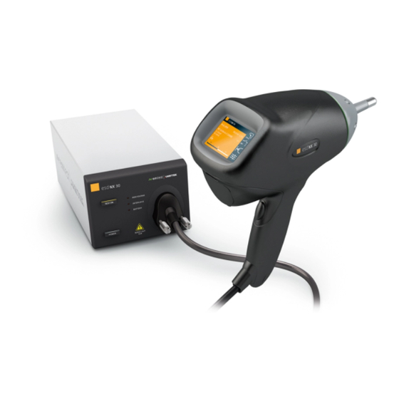
Ametek esd NX30.1 Quick Start Manual And Safety Instructions - Page 13
Browse online or download pdf Quick Start Manual And Safety Instructions for Switch Ametek esd NX30.1. Ametek esd NX30.1 17 pages.

AMETEK CTS
5.1.2
Ports (esd NX30, NSG 438 models only)
This port is indented to allow the user to connect external signals in order to remote control the generator, as well as to con-
nect external accessories like the charge removing device. See tables and graphs below for detailed signal description and
drive circuitry information.
Connector J3: Pin Assignment
Pin
Signal Name
1
EXT_TRIGGER
2
NC
3
NC
4
EUT_FAIL
5
GND
6
NC
7
Charge remove
8
GND
9
+15V
Ext. Trigger (esd NX30 only):
The following circuit is built in behind the external trigger input connector. This function is similar to the function of the yellow
trigger knob on the handle. Trigger signal active low, i.e. to be pulled to ground.
Charge removing connection:
This function is to drive an external bleedoff switch option or an external relay.
Quick Start and Safety Guide
Description
External trigger input
-
-
EUT failure input
(reserved for future use)
Earth
-
Charge remover drive output
Earth
Voltage output (max 500 mA)
V 1.0
ESD Simulators
13 / 17
