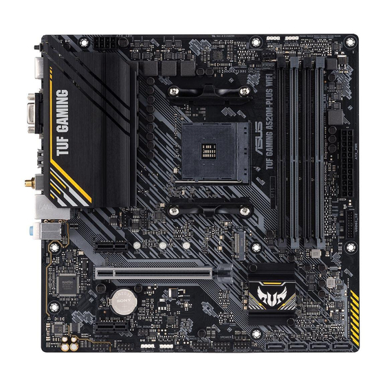
Asus 90MB14Y0-M0EAY0 Manual - Page 13
Browse online or download pdf Manual for Motherboard Asus 90MB14Y0-M0EAY0. Asus 90MB14Y0-M0EAY0 30 pages.

•
System warning speaker (4-pin SPEAKER)
This 4-pin header is for the chassis-mounted system warning speaker. The speaker
allows you to hear system beeps and warnings.
•
ATX power button/soft-off button (2-pin PWRSW)
This header is for the system power button. Pressing the power button turns the
system on or puts the system in sleep or soft-off mode depending on the operating
system settings. Pressing the power switch for more than four seconds while the
system is ON turns the system OFF.
•
Reset button (2-pin RESET)
This 2-pin header is for the chassis-mounted reset button for system reboot without
turning off the system power.
1.2.2
Rear panel connectors
1
6
1.
PS/2 Keyboard/Mouse combo port. This port is for a PS/2 keyboard or mouse.
2.
Video Graphics Adapter (VGA) port. This 15-pin port is for a VGA monitor or other
VGA-compatible devices.
3.
Ethernet port. This port allows Gigabit connection to a Local Area Network (LAN)
through a network hub. Refer to the table below for the Ethernet port LED indications.
Ethernet port LED indications
Activity/Link LED
Status
Off
Orange
Orange (Blinking) Data activity
Orange (Blinking
then steady)
ASUS TUF GAMING A520M-PLUS
2
7
8
Description
Status
No link
Off
Linked
Orange
Green
Ready to wake
up from S5 mode
9
10
Speed LED
Description
10Mbps connection
100Mbps connection
1Gbps connection
3
4
5
6
11
Speed
Activity Link
LED
LED
Ethernet port
1-5
