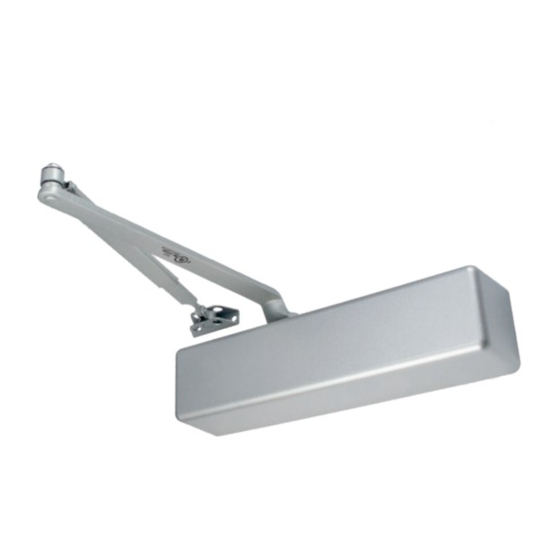
Dorex 1901 Installation Instructions
Browse online or download pdf Installation Instructions for Door Opening System Dorex 1901. Dorex 1901 2 pages.

PARALLEL ARM INSTALLATION
CLOSER MOUNTED ON DOOR ON PUSH SIDE
This drawing shown is RIGHT HAND DOOR, for LEFT HAND DOOR install opposite
1-3/8
1-3/8
(35)
(35)
11/16
1
1
(17)
(25)
(25)
5/16"
4-3/4
(8)
(120)
S
L
DA
BC
SPRING POWER ADJUSTMENT
INCH
(mm)
11-1/8
(283)
Soffit
Parallel Arm
Bracket
RIGHT
HAND
Door opens to
the outside
Main
Arm
Preload 45°
Forearm
Soffit
Parallel Arm
Bracket
LEFT
HAND
Door opens to
Hold-Open
the outside
Adjusting Nut
Main
Arm
45° Preload
Page 4
INCH
(MM)
Hinges
A
Centerline
INSTALLATION DIMENSIONS
3-3/8
(86)
A
OPENING
INCH
mm
9/16
(14)
TO 120°
9-1/8
241
9/16
(14)
121°TO 180°
178
5-7/8
B
DOOR CLOSER INSTALLATION
1. Refer to installation instructions supplied with door closer.
2. Adjust spring power to match door size as indicated in chart on page 1.
3. Mount door closer on door using dimensions for the selected door opening
angle, with speed control valves facing away from the hinges.
4. Mount parallel arm bracket on frame stop soffit using dimensions for the
selected door opening angle.
5. Disconnect main arm from the forearm. Using a wrench on the door closer
bottom shaft rotate shaft about 45° towards the hinges and place main arm
on door closer top shaft and attach with screw.
6. Attach forearm (friction arm) shoe on the parallel arm bracket with two
machine screws. Position hold-open adjusting nut on top for right hand (RH)
door or bottom for left hand (LH) doors.
7. Close door, loosen hold-open adjusting nut (turn clockwise), and position
main arm parallel to the door surface and adjust length of threaded rod of
forearm to connect to the main arm. Secure forearm (friction arm) to main
arm with screw.
DOOR CLOSER ADJUSTMENTS
1. Refer to adjustment instructions supplied with door closer and pictorials on
page 1.
2. Adjust closing speed and latch speed so that the door closes for a 120° door
opening position within 6-7 seconds, evenly divided between sweep speed
and latch speed.
3. To adjust the hold-open position, open the door to the desired opening angle
and tighten the adjusting nut (turn counterclockwise) on the friction arm.
Close and open the door and verify that the hold open works.
4. Adjust backcheck if required.
COVER INSTALLATION
1. Place cover over door closer and attach with supplied screws.
2. Place shaft cover on the exposed door closer shaft.
WITH FRICTION HOLD OPEN ARM (1901-ARMF)
INSTALLATION INSTRUCTIONS
REGULAR MOUNT
(PULL SIDE)
B
INCH
mm
Illustrations for reference only, actual door closer style and shape and arm may vary.
6-1/8
156
2-9/16
65
SPRING POWER ADJUSTMENT
SPRING POWER SIZE
1
2
3
4
5
6
CCW : Counterclockwise CW: Clockwise
* pound (force)
SPRING POWER ADJUSTMENT
1901-ARMF-INST 2021-01
TOP JAMB MOUNT
(PUSH SIDE)
TURNS
REQUIRED
5 lb-f*
8 TURNS CCW
8.5 lb-f*
4 TURNS CCW
Factory Preset
0 TURNS
4 TURNS CW
8 TURNS CW
12 TURNS CW
HIGHER
Clockwise (CW)
LOWER
Counterclockwise (CCW)
Refer to installation instructions supplied with door closer for more details
PARALLEL MOUNT
(PUSH SIDE)
DOOR HANDING
CONTROL RANGE
Backcheck
_
(–) Softer
(+) Harder
+
Closing
1
F
(F) Faster
(S) Slower
S
F
2
S
Latching
(F) Faster
3
(S) Slower
Page 1
